Кімнатний обігрівач електроламповий
Формула / Реферат
1. Кімнатний обігрівач електроламповий для обірву зачинених побутових кімнат та приміщень, який містить вертикальний циліндричний корпус з розміщеними усередині горизонтальними поперечними перегородками, котрі розділяють внутрішню порожнину на відсіки, і який опирається на відсіки, і який опирається на закріплені до нижньої перегородки похилі лапи, який відрізняється тим, що нагрівальними елементами обігрівача є електричні лампи розжарювання, підключені поярусно по одній електролампі в кожному відсіку під віутом 90° по відношенню одна до другої по гвинтовій лінії, в горизонтальному положенні, які забезпечують контактний нагрів повітря, τакож у кожному відсіку установлені вертикальні вузькі стояки, які розміщені під кутом 120° між собою та служать для закріплення до однієї із них у кожному ярусі по одному керамічному електропатрону.
2. Кімнатний обігрівач по пп. 1 і 2, який відрізняється тим, що його циліндрична обичайка по всій висоті виконана з вертикальними дрібними гофрами, збільшуючими теплопередавальну поверхню обігрівача, скріплена фіксаторами з нижньою перегородкою корпуса, а в тілі обичайки проти кожної електричної лампи розжарювання у заглибинах гофр виконано по одному отвору для візуального контролю стану, електроламп розжарювання.
3. Кімнатний обігрівач пo пп. 1 і 2, який відрізняється тим, що вертикальні вузькі стойки одного відсіку повернуті по відношенню до таких же стойок суміжного відсіку на 90° по гвинтовій лінії знизу доверху, одночасно служать опорами пoперечним перегородкам корпуса та кришці кожуха, а до останньої закріплений диск щільно до верхнього торця обичайки кожуха розміром трохи більшим діаметра обичайки кожуха, закриваючий всі верхні отвори гофр, утворюючи обігрівач закритого типу.
4. Кімнатний обігрівач по пп. 1 та 2, відрізняється тим, що його конструкція дозволяє відділяти кожух, поперед вийнявши фіксатори із своїх гнізд унизу обичайки, для заміни електроламп розжарювання, а деталі кожуха виконані із тонколистового алюмінію, що і дозволяє знижувати металомісткість кімнатного обігрівача електролампового.
Текст
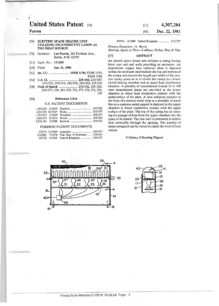
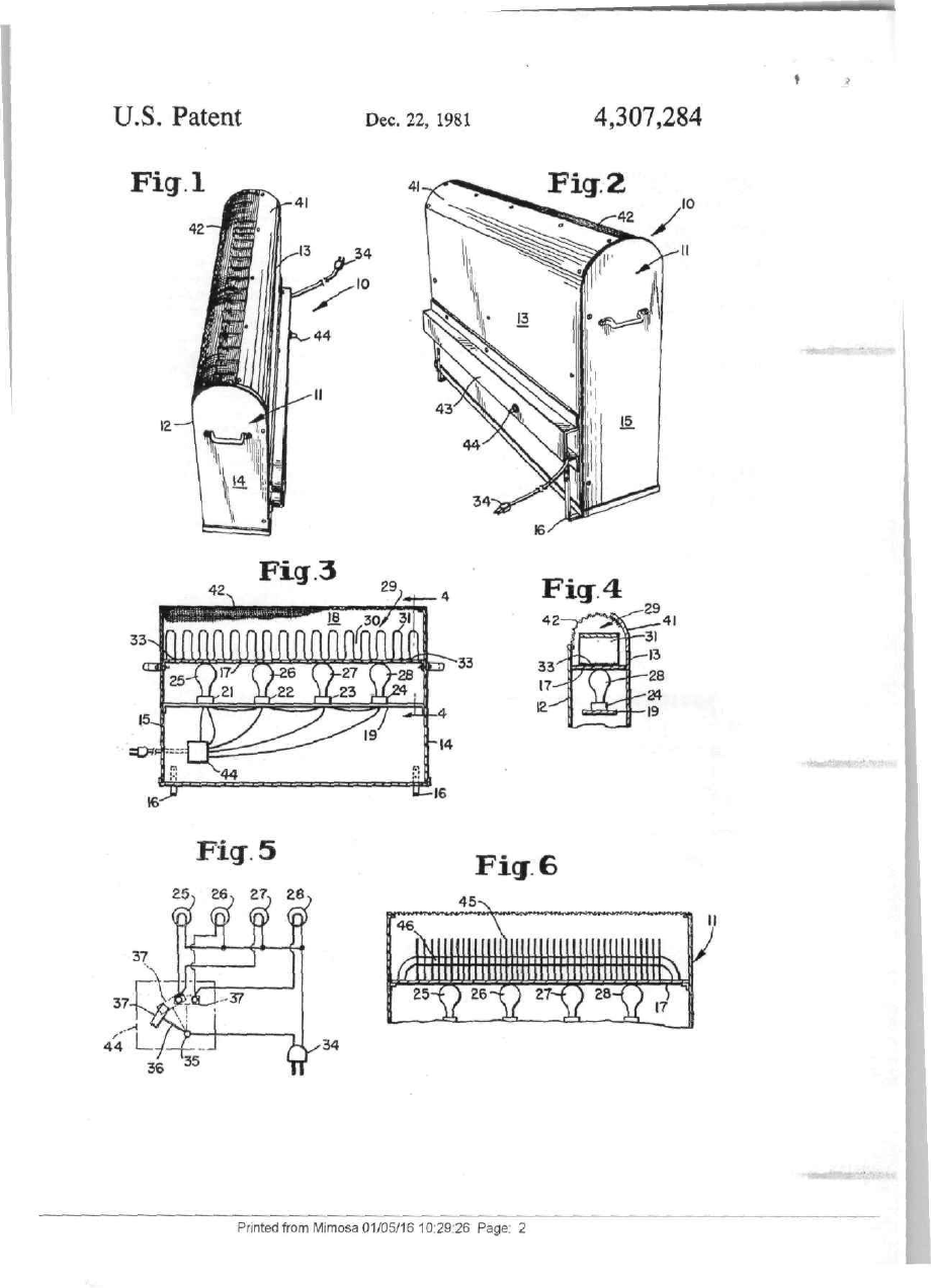
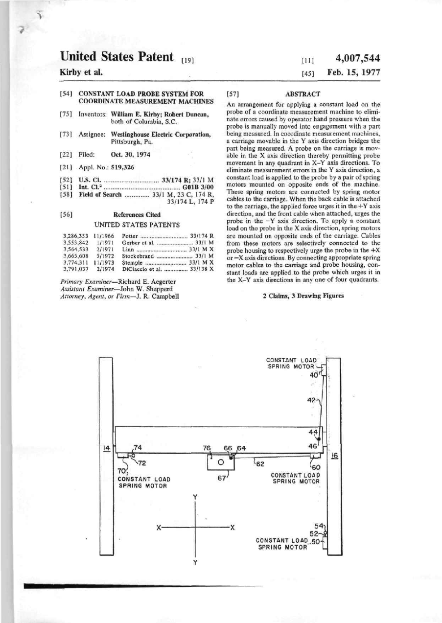
United States Patent П] 9 [11] 4,307,284 Perron [45] Dec. 22, 1981 [54] ELECTRIC SPACE HEATER UNIT UTILIZING INCANDESCENT LAMPS AS THE HEAT SOURCE [76] Inventor Leo Perron, 362 Forbush Ave , Berlin, N H 03570 [21] Appl. No 117,083 [22] Filed Jan. 31, 1980 f5i] Int. aj H05B 1/00; F24H 3/00, F24H 9/02 219/342, 219/347, [52] U-S. CI. 219/352, 219/354, 219/358, 219/365, 219/552 219/342, 353-355, \5S] Field t>f Search 219/377. 358, 365-370, 374, 375, 376, 552, 220, 347 m References Cited U S PATENT DOCUMENTS 1,294,269 1,652,438 1.713 013 J,926 473 2,938 101 2/1919 12/1927 V1929 9/1933 5/1960 Hopkms Hicks Wandless Wood Borzner 219/552 219/377 219/377 219/365 219/365 FOREIGN PATENT DOCUMENTS 135371 11/1949 Australia 2363006 7/1974 Fed Rep nfGermany 504722 4/1939 United Kingdom 219/375 219/365 219/377 598741 2/J948 United Kingdom Primary Examiner—A Bartis Attorney, Agent, or Firm—LeBIanc, Nolan, Shur & Nies ABSTRACT 157] An electric space healer unit includes a casing having front, rear and end waJb providing an enclosure An imperforate copper heat collector plate is disposed wjthin the enclosure mtermediate the top and bottom of the casing and extends the length and width of the inte rior casing space so as to divide the casing to a lower closed heating chamber and an upper heat distribution chainber A plurality of conventional frosted 75 or 100 watt incandescent lamps are provided m the lower chamber m direct heat conductive contact with the undersurface of the plate A heat radiation member in the form of a sinuous metal strip or a plurality of metal fins on a common metal support is disposed in the upper chamber m direct conductive contact with the upper surface of the plate The top of the casing has an open ing for passage of heat from the upper chamber into the space to be heated The rear wail is contoured to rellect heat outwardly through the opening The number of lamps energized can be varied to adjust the level of heat output 8 Caims, б Drawing Figures Ji^ttS^, ^-SeSi^. ^ 3]9/377 -rf Printed from Mimosa 01/05/16 10 29 24 Page 1 U.S. Patent 4,307,284 Dec. 22, 1981 Fig 2 "«^-^•' •-' " Fig3 18 '^—rV Ficr4 3 0 / 31 33 LD^33 ЇЇЙзЧЧІ*" Fig 5 Fig 6 £5> ге, £7, ге. -ТЇЙЖИї» Printed from Mimosa 01/05/16 10 29 26 Page 2 4!раЩ!8ІЯ№І!Р^Щ-' 7,284 ELECTRIC SPACE HEATER UNIT UTILIZING INCANDESCENT LAMPS AS THE HEAT SOURCE gfHt., • •аыы ^ і 2 PREFERRED EMBODIMENTS The space heater 10 comprises a closed bottom enclo sure 11 having parallel front and rear walls 12 and 13 This invention relates to space heaters and is particu j fixed to shorter end walls 14 and 15 These walls are preferably of 24 gauge sheet mefaf I he enclosure II is iariy concerned with space healer apparatus wherein mounted on four mturned corner legs 16 so as to be heat derived from a plurality of electric lamps is distnbslightly spaced above a support surface such as a tloor, uted Ш a novel way thereby allowing free air movement into the enclosure The invention will be described in its preferred em 0 space bodiment wherein a plurality of more or less conven Near Its upper end the space within the enclosure is tional electric lamps, topically four of rated wattage, are bridged by an imperforate fiat heat collector plate 17 mounted Ш an enclosing casing with their glass bulbs ш that IS generally horizontal Plate 17 is of substantially contact with a plate of high heat conductivity, and an the width and length of the space, thereby providing a increased area radiation surface distributes heat from 5 closed bottom heat distribution chamber 18 above it the plate within the enclosure Plate 17 is preferably a sheet of The concept of deriving space heating from a plural thin copper, about 14 gauge, preferably slightly flexible, ity ОЇ electric lamps mounted Withm an enclosure has that ISfixedto the inner sides of the enclosure end walls been proposed as evidenced by U S Pat Nos to Sharpe Below plate 17 the space is bridged longitudinally by 1,064,258, Muir el di 2,051,456, Borgner 2,520,830, 0 a honzontal lamp mounting strip 19 on which are dis Covault et al 2,919,338 and Borgner 2,938,101 How posed four evenly spaced lamp socketi; 21 22 23, and ever, Sharpe and Muir et al, disclose heat concentra 24 These sockets may be the usual threaded type fur tion by shaped reflectors, Borgner utilizes radiation accepting screw base lamps, and lamps 25^28 are from infra red lamps and Covalt et al discloses lamps mounted therein associated with a relatively complete heat absorbtion 5 In the invention the lamps 25-28 are adapted to burn "Чї^^ concentration structure upright, base down which is their longest life position, The present invention distinguishes over such prior and the glass bulbs engage snugly the smooth underside art by provision of novel structurally simple yet unex of plate 17 m heat transmitting contact Since plate 17 is pectedly efficient heat transfer arrangements, and such preferably longitudinally flexible it may give slightly to is the major object of the invention 0 enable lamp replacement, and when the lamps are in It is a further object of the invention to provide an position the slighlly flexed condition of plate 17 ensures good area snug heat transfer contact with all lamps unusually efficient space heater wherein heat from a For ease Ш lamp replacement support І9 can be made plurality of relatively low wattage electric lamps is adjustable by means of suitable screw and slot arrange efficiently utilized A more specific object of the invention is to provide .5 mcnts at its supported ends In the form shown m FIGS 1 and 3 the increased a novel space heater, the interior of which is separated area heat radiation surface is provided by a single sinu by a metal plate into a lower heating chamber and an ous strip 29 of highly heat conductive melal, such as 14 upper heat distribution chamber wherein a plurality of gauge copper In practice m a working embodiment electric lamps, which may, for example, be the usual conventional gas-filled 75 or 100 watt lamps conven Ю plate 17 is about six inches wide, the width of the space between the front and rear walls 12 and 13 and strip 29 tionally used for illumination, arc disposed ш the lower may be above five inches wide bent into longitudinally chamber in direct heat transfer with the lower side of spaced convulutions that extend up on loops 31 about that metal plate, which is of copper or other metal of SX inches from the plate 17 The lower ends of each I high heat conductivity, and an expanded area heat radi valley 30 between the loops are fixed m good heat con ation means comprising a metal structure having convo ductive relation, as by soldered junctures indicated at 33 lutions or fins IS secured in the upper chamber in direct which permanently join stnp 29 to plate 17 Where heat transfer contact with the upper side of the metal plate 17 IS six inches wide and thirty inches long, the plate, with heat from the upper chamber being passed sinuous strip 29 prior to bending was about five inches into the space to be heated through a top opening ш the wide and one hundred and forty mclies long casing In the preferred embodiment four lamps are used in the source of heat The lamps are connected m circuit BRIEF DESCRIPTION OF DRAWINGS with a three position switch 44 whereby none, only two FIG 1 IS a generally perspective view taken from or all four may be energized as indicated in FIG 5 As above and to one side showmg a portable space heater shown Ш FIG 5 one wire from the usual plug 34 may be according to a preferred embodiment of the invention connected to switch terminal 35 which rockably FIG 2 IS a generally perspective rear view of the mounts switch arm 36 shown m non-energizmg posi heater of PIG 1, tion Switch arm 36 may be relatively rocked to a low FIG 3 IS a section dia grammatically showing the heat position wherein blade 37 acts to connect only two arrangement of lamps, heat collector plate and radiation lamps 25 and 27 into the live circuit, or to connect all area m the heater of FIGS 1 and 2, four lamps into the live circuit Thus the heater as dis closed has two effective level heat outputs FIG 4 (s a frdgmenlary section substantially on line 4—4 in FIG 3 showing detail of the heat transfer mode At the upper end of the casing as bhown the rear wall FIG 5 is a schematic showing of a circuit for energiz may be curved for about 90° to provide a lop wall sec mg two or four lamps for selective space heating, and tion 41 that may act partly as a heat reflector and the front of the lop wall may be a similarly curved open FIG 6 IS a fragmentary view showing another em mesh wire member 42 that permits exchange of hedled bodiment wherein fins conduct and radiate the heat air while protecting against accidental direct contact from the heat collector plate Printed from Mimosa 01/05/16 10 29 28 Page 3 4,307,284 with stnp 29. Alternatively the top of the heater may be flat with wire member 42 being a flat strip of perforated aluminum mesh As shown in F I G . 2, the wires from the plug 34 may enter a protective tunnel 43 on the rear wall, with the switch 44 disposed wilhm the tunnel. F I G . 6 illustrates a further embodiment. T h e casing structure IS the same as m F I G S . 1-4 including plate 17 and the contacting lamps. In F I G 6 the convululed strip 29 IS replaced as a heat distribution device by a multiplicity of spaced thin metal fins 45 secured on a rigid metal rod m lube 46 that has Us opposite ends fixedly mounted on the casing walls. The lower edges of the fins are m tight contact with the upper surface of heat collector plate 17 and may be soldered thereto for better heat conduction. Actually the fin and rod struc tures may be similar to that used m a conventional base board heater where the rod is hollow and carries heated fluid, except thai here the rod serves only to support and locate the fins conventional lamps are usually designed for 750 hours life and may last longer. The invention may be embodied in other specific forms without departing from the spirit or essential 5 characteristics thereof. The present embodiments are therefore to be considered in all respects as illustrative and not restrictive, the scope of the invention being indicated by the appended claims rather than by the foregoing description, and all changes which come 10 within the meaning and range of equivalency of the claims are ttiereiore intended to be embraced therein !5 20 The lampb 25-28 arc the sole sources of heat energy. The highly conductive copper plate 17 contacting the lamps serves as a heat collector and transfers the heat energy to the strip convulutions or fins, identified m the claims broadly as increased surface area heat radiation 25 means, and heated air derived therefrom is applied to the room or other space to be heated. In practice several of these 40O watt space heaters have been used to heat rooms in a dwelling in New Hampshire, and it has been found that they heated the rooms comfortably, often to 70°-73° F,, under external temperature conditions that normally required opera tion of the oil-fired central heatmg system for the same comfort. The savings in heating costs are large, since the central heatmg system can be maintained inoperalive during at least much of the day. The enclosure ensures that little or no disturbing stray light from Ihe lamps will be experienced. The units are inexpensive and require no servicing except lamps replacement The lamps used are conventional gas-filled inside frost incandescent lamps that are primarily sold for lighting and can be purchased in any grocery or drug sioie. As compared with conventional electric heaters available today, the units of the inven tion consume considerably less power than ihe usual 1600 watt or more heaters on the market. Units of the invention m use have been found to cost about I і cents per hour for power. 30 35 40 45 Since the units are portable they may be moved from room to room or to cool spots ш a space, to provide the 50 sole heat needed for comfort or to aid the centra] heat ing system F o r example, on a very cold day, even with sub-zero temperatures outside, a house could be heated initially up to temperature by the central heating system and then, during the balance of the day, the central 55 heating system could be disabled and the interior heal level maintained by one or more units of the invention An openable door may be provided in either the front or rear walls of the casing for access to the lamps. These 60 What IS claimed and desired (o be secured by Letters Patent IS; 1. In a space heater unit, a casing having front, rear and end walls providing an enclosure, a substantially imperforate heat collector plate of high heat conductive material extending within the enclosure, said plate being disposed intermediate the top and bottom of the casing and extending substantially the length and width of the interior space defined by said casing so as to divide the casing interior into an upper heaJ distribution chamber and a lower closed heating chamber, a plurality of elec tric lamps mounted withm said lower chamber, each of said lamps having glass bulbs in direct heat exchange contact with the underside of said plate, and increased surface area heat radiation means mounted in said upper chamber in direct heat conductive contact with and along the upper surface of said heat collection plate, the upper part of said casing having an opening extending over at least part of said top wail and through which heat from said heat conductor plate and radiation means passes into the space to be heated. 2. In the space heater defined in claim 1, said in creased surface area heat radiation means being a con voluted stnp of metal, the convolutions being spaced lengthwise of the strip and the valleys between convo lutions being in direct rigid heat conductive contact with said plate. 3 In the space heater defined m claim 1, said in creased surface area heat radiation means being a longi tudinally spaced series of metal fins mounted on a com mon metal support and each having its lower edge in direct contact with the upper surface of said plate. 4. In the space heater defined in claim 1, means for selectively energizing all or a selected minor group of said lamps, for differential heat output. 5, In the space healer defined in claim 1, said lamps being conventional gas-filled inside frost incandescant lamps of the type normally used for lighting. б In the space heater defined in claim 1, means pro viding a protective mesh screen over said opening. 7. In the space heater defined in claim 1, said plate being a longitudinally flexible metal strip extending substantially entirely across the interior of the enclo sure. 8 In Ihe space heater defined in claim 1, said rear wall being contoured and arranged to reflect and direct heat outwardly through said opening. 65 Printed from Mimosa 01/05/16 10 29 30 Page 4 illaittwgTttfflEl»*-»
ДивитисяДодаткова інформація
Назва патенту англійськоюRoom electric-lamp heater
Автори англійськоюKara Petro Pylypovych
Назва патенту російськоюКомнатный обогреватель электроламповый
Автори російськоюКара Петр Филиппович
МПК / Мітки
МПК: F24H 3/04
Мітки: кімнатний, електроламповий, обігрівач
Код посилання
<a href="https://ua.patents.su/4-40668-kimnatnijj-obigrivach-elektrolampovijj.html" target="_blank" rel="follow" title="База патентів України">Кімнатний обігрівач електроламповий</a>
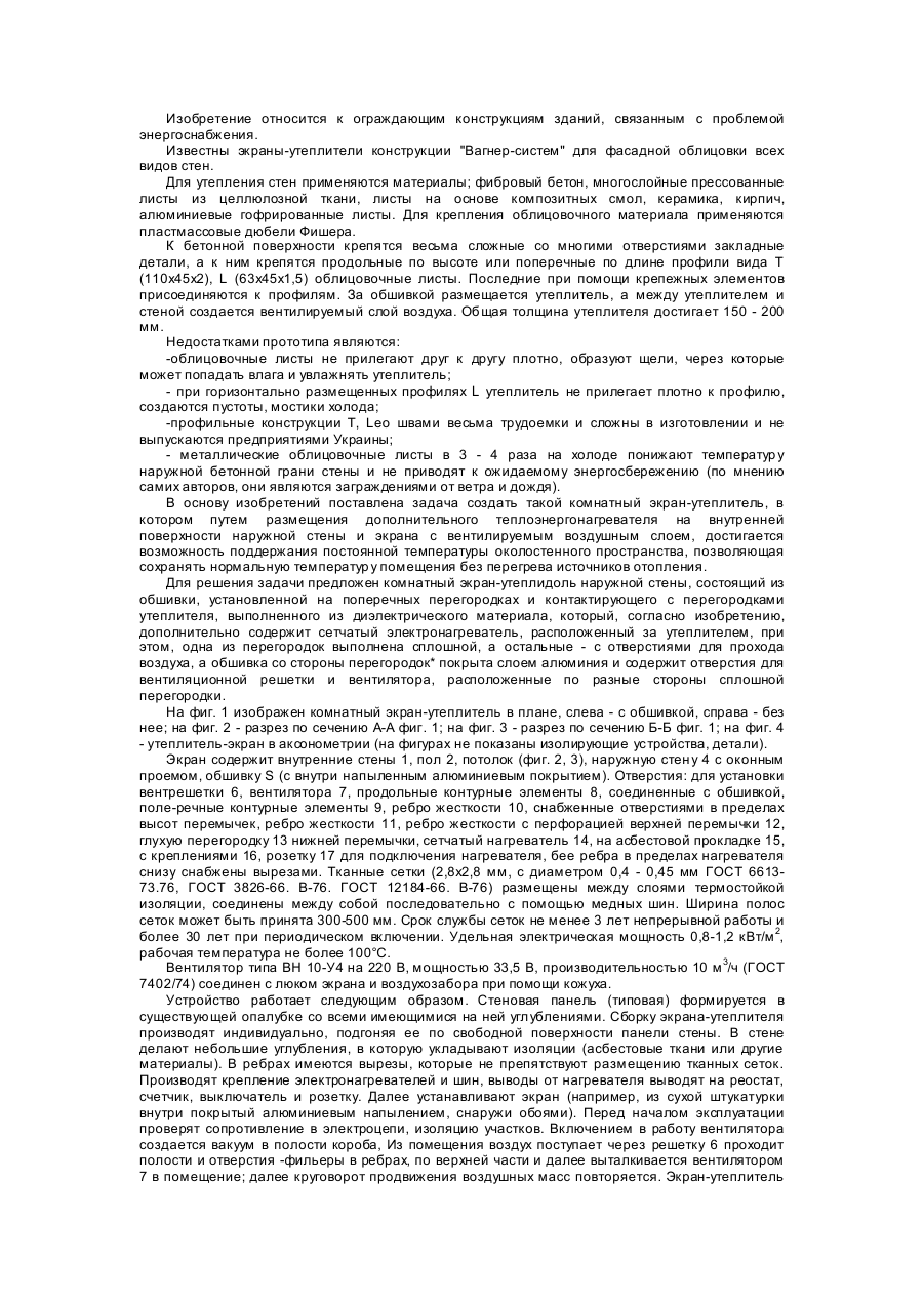
Кімнатний екран-утеплювач зовнішньої стіни
Номер патенту: 13948
Опубліковано: 25.04.1997
Автори: Семко Юрій Миколайович, Злобін Генадій Карпович, Дорофеєв Віталій Степанович, Лівінський Олександр Михайлович, Тимофеєв Микола Іванович
МПК: E04B 1/74, E04B 1/76, E04C 2/34
Мітки: кімнатний, стіни, екран-утеплювач, зовнішньої
Формула / Реферат:
Комнатный экран-утеплитель наружной стены, состоящий из обшивки, установленной на поперечных перегородках и контактирующего с перегородками утеплителя, выполненного из диэлектрического материала, отличающийся тем, что он дополнительно содержит сетчатый электронагреватель, расположенный за утеплителем, при этом одна из перегородок выполнена сплошной, а остальные - с отверстиями для прохода воздуха, а обшивка со стороны перегородок покрыта...
Спосіб визначення розміру переходу через “мертву точку” важелів механізму відкривання та закривання кришок розвантажувальних люків бункерного вагону
Номер патенту: 24188
Опубліковано: 07.07.1998
Автори: Трубачов Юрій Олексійович, Штанцель Юрій Анатолійович, Чебикін Вячеслав Михайлович
Мітки: точку, механізму, мертву, люків, закривання, переходу, розміру, спосіб, розвантажувальних, відкривання, важелів, визначення, вагону, кришок, бункерного
Формула / Реферат:
Способ определения величины перехода через "мертвую точку" рычагов механизма открывания и закрывания крышек разгрузочных люков бункерного вагона, включающего продольный приводной вал с жестко закрепленными на нем двуплечими рычагами и изогнутые тяговые рычаги, каждый из которых одним концом шарнирно прикреплен к соответствующему плечу двуплечего рычага, а вторым концом - к поворотной крышке разгрузочного люка, заключающийся в том,...
Попередній патент: Пристрій для ущільнення списа в отворі при його введенні до ємності, яка знаходиться під тиском
Наступний патент: Спосіб виробництва мінеральних волокон ( варіанти ) та пристрій для його здійснення
Випадковий патент: Пристрій відтворення відеосигналів