Спосіб визначення розміру переходу через “мертву точку” важелів механізму відкривання та закривання кришок розвантажувальних люків бункерного вагону
Номер патенту: 24188
Опубліковано: 07.07.1998
Автори: Трубачов Юрій Олексійович, Чебикін Вячеслав Михайлович, Штанцель Юрій Анатолійович

Формула / Реферат
Способ определения величины перехода через "мертвую точку" рычагов механизма открывания и закрывания крышек разгрузочных люков бункерного вагона, включающего продольный приводной вал с жестко закрепленными на нем двуплечими рычагами и изогнутые тяговые рычаги, каждый из которых одним концом шарнирно прикреплен к соответствующему плечу двуплечего рычага, а вторым концом - к поворотной крышке разгрузочного люка, заключающийся в том, что измерительное устройство базируют по осям крепления тягового рычага и приводят его в контактное взаимодействие с наружной поверхностью приводного вала, отличающийся тем, что измерение осуществляют посредством нерастяжимой гибкой нити с прикрепленными к ней узлами для базирования и отсчетным узлом для измерения ее длины, указанную гибкую нить располагают последовательно с двух противоположных сторон приводного вала и в каждом положении осуществляют измерение ее длины, при этом величину перехода через "мертвую точку" определяют как произведение разности полученных двух показаний отсчетного узла на коэффициент пересчета.
Текст
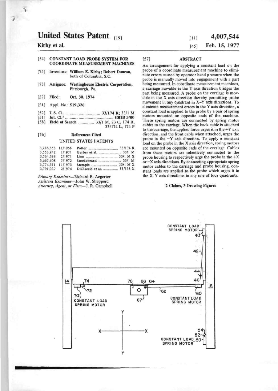
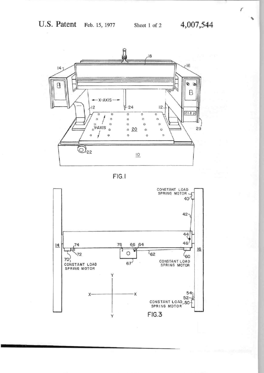
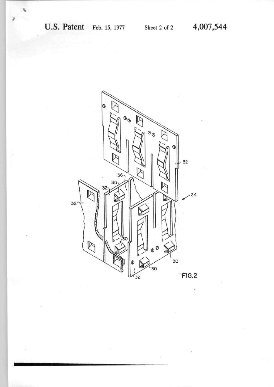
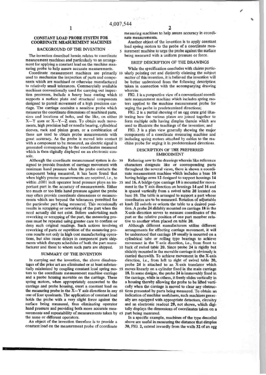
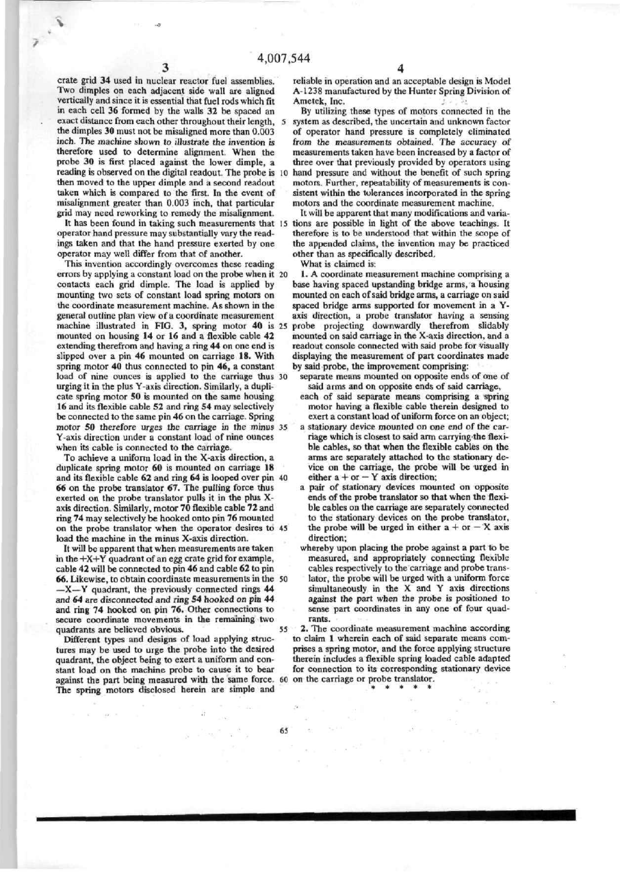
United States Patent [,9j [11] 4,007,544 Kirby et al. [45] Feb. I S , 1977 [54] CONSTANT LOAD PROBE SYSTEM FOR COORDINATE MEASUREMENT MACHINES [75] Inventors: William E. Kirby; Robert Duncan, both of Columbia, S.C. [73] Assignee: Westinghouse Electric Corporation, Pittsburgh. Pa. [22] Filed: Oct. 30, 1974 [21] Appl. No.: 519,326 [52] U.S. CI [51 ] Int. С1.2 [58] Field of Search [56] 33/174 R; 33/1 M GOIB 3/00 33/1 M, 23 C, 174 R, 33/174 L, 174 P References Cited UNITED STATES PATENTS 3,286.353 t 1/1966 3.553.842 1/1971 3,564,533 2/1971 3,665,608 5/1972 3,774,311 11/1973 3.791,037 2/1974 Potter Gerber et al Linn Stockebrand Stemple DiCiaccio et al Primary Examiner—Richard E. Aegerter Assistant Examiner—John W. Shepperd Atiorney, Agent, or Firm—J. R. Campbell 33/174 R 33/1 M 33/1 M X 33/1 M 33/1 MX 33/138 X [57] ABSTRACT An arrangement for applying a constant load on the probe of a coordinate measurement machine to elimi nate errors caused by operator hand pressure when the probe is manually moved into engagement with a part being measured. In coordinate measurement machines, a carriage movable in the Y axis direction bridges the part being measured. A probe on the carriage is mov able in the X axis direction thereby permitting probe movement in any quadrant in X-Y axis directions. To eliminate measurement errors in the У axis direction, a constant load is applied to the probe by a pair of spring motors mounted on opposite ends of the machine. These spring motors are connected by spring motor cables to the carriage. When the back cable is attached to the carriage, the applied force urges it in the +Y axis direction, and the front cable when attached, urges the probe in the —Y axis direction. To apply a constant load on the probe in the X axis direction, spring motors are mounted on opposite ends of the carriage. Cables from these motors are selectively connected to the probe housing to respectively urge the probe in the -1-Х or —X axis directions. By connecting appropriate spring motor cables to the carriage and probe housing, con stant loads are applied to the probe which urges it in the X-V axis directions in any one of four quadrants. 2 Claims, 3 Drawing Figures CONSTANT LOAD SPRING MOTOR 40' 42 14 16 60 CONSTANT LOAD SPRING MOTOR CONSTANT LOAD SPRING MOTOR 5452--! CONSTANT LOAD SQ-f SPRING MOTOR" L U.S. Patent Feb. 15, 1977 Sheet 1 of 2 4,007,544 FIG. CONSTANT LOAD SPRING MOTOR 40' 42 14 16 CONSTANT LOAD SPRING MOTOR 60 CONSTANT LOAD SPRING MOTOR 54i 52--І CONSTANT L0AD_,50 SPRING MOTOR L F1G.3 U . S . Patent Feb. 15, 1977 Sheet 2 of 2 4,007,544 П0.2 ,7.544 ^ • ;• . measuring machines to help assure accuracy in coordi nate measurements. Another object of the invention is to apply constant load spring motors to the probe of a coordinate meaBACKGROUND OF THE INVENTION 5 surement machine to urge the probe against the surface being measured with a uniform pressure or force. The invention described herein relates to coordinate measurement machines and particularly to an arrange BRIEF DESCRIPTION OF THE DRAWINGS ment for applying a constant load on the machine mea While the specification concludes with claims parlicsuring probe to help assure accurate measurements. Coordinate measurement machines are primarily 10 ulariy pointing out and distinctly claiming the subject used to mechanize the inspection of parts and compo matter of this invention, it is believed the invention will nents which are machined or otherwise manufactured be better understood from the following description to relatively small tolerances. Commercially available taken in connection with the accompanying drawing machines conventionally used for carrying out inspec wherein; tion processes, include a heavy base casting which 15 FIG. 1 is a perspective view of a conventional coordi supports a surface plate and structural components nate measurement machine which includes spring mo designed to permit movement of a high precision car tors applied to the machine measurement probe for riage. The carriage contains a sensitive probe which urging the probe in predetermined directions; measures the coordinate dimensions of machined parts, FIG. 2 is a partial showing of an egg crate grid illussizes and locations of holes, and the like, on either 20 trating how the various plates are joined together to X—Y axes or X—Y—Z axes. To obtain such move form multiple cells having dimples therein which are ments, high precision ball or needle bearing, cylindrical used to illustrate the teachings of the invention; and sleeves, rack and pinion gears, or a combination of FIG. 3 is a plan view generally showing the major these are used to obtain probe measurements with components of a coordinate measuring machine and great accuracy. As the probe is moved into contact 25 including spring motors attached by cables to the ma with a component to be measured, an electric signal is chine probe for urging it in predetermined directions. generated corresponding to the coordinates measured DESCRIPTION OF THE PREFERRED which is then digitally displayed on an electronic con EMBODIMENT sole. Although the coordinate measurement system is de 30 Referring now to the drawings wherein like reference signed to provide freedom of carriage movement with characters designate like or cooresponding parts minimum hand pressure when the probe contacts the throughout the several views, there is shown a coordi component being measured, it has been found that nate measurement machine which includes a base 10 when highly precise measurements are required, i.e., to having bridge arms 12 designed to support housings 14 within .0001 inch operator hand pressure plays an im 33 and 16. A bridge-type carriage 18 is mounted for move portant part in the accuracy of measurements. Either ment in the Y axis direction on housings 14 and 16 and too much or too little hand pressure against the probe is spaced vertically from a swivel table 20 located on may often provide coordinate dimensions or measure base 10. The table is arranged to support a part whose ments which are beyond the tolerances permitted for coordinates are to be measured. Rotation of adjustable the particular part being measured. This occasionally 40 knob 22 swivels or orients the table to a desired posi results in scrapping or reworking of the part when the tion. A probe 24 slidabty mounted on carriage 18 in the need actually did not exist. Before undertaking such X-axis direction serves to measure coordinates of the reworking or scrapping of the part, the measuring pro part or the relative position of one part member rela cess must be repeated using greater care to confirm or tive to another when placed on table 20, deny such original readings. Such actions involving 45 Although different manufacturers utilize different reworking of parts or repetition of the measuring pro arrangements for effecting carriage movement, it will cess results not only in high cost manufacturing opera be understood that carriage 18 usually is mounted on a tions, but also cause delays in component parts ship cylindrical tube or rolling type bearings to achieve ments which disrupts schedules of both the part manu movement in the Y-axis direction, i.e., from front to facturer and those to whom such parts are shipped. 50 back of swivel table 20. Since probe 24 is rigidly but slidably mounted in the movable carriage it obviously is SUMMARY OF THE INVENTION carried therewith. To achieve movement in the X-axis In carrying out the invention, the above disadvan direction, І.Є., from left to right of swivel table 20, tages of the prior art are eliminated or at least substan probe 24 is attached to an X-axis translator which tially minimized by coupling constant load spring mo 55 moves linearly on a cylinder fixed in the mam carriage tors to the coordinate measurement machine carriage 18. In some designs, the probe 24 is immovably fixed in and a probe housing movable on the carriage. These the carriage, while in others, it freely slides vertically in spring motors, when appropriately connected to the a housing thereby allowing the probe to be lifted verti carriage and probe housing, exert a constant load on cally when the carriage is moved to clear any obstructhe measuring probe in the X—Y axis directions in any 60 tions presented by parts being measured. To obtain an one of four quadrants. The application of constant load indication of machine usefulness, such machines gener holds the probe with a very slight force against the ally are equipped with appropriate detectors, circuitry surface being measured, thus eliminating operator and an electronic readout 29, not shown, which digi hand pressure and providing both more accurate mea tally displays the dimensions of coordinates taken on a surements and repeatability of measurements taken by 65 part being measured. the same or different operators. In a specific example, machines of the type describd An object of the invention therefore is to provide a above are useful in measuring the distance that dimples constant load on the measurement probe of coordinate 30, FIG. 2, extend inwardly from the walls 32 of an egg CONSTANT LOAD PROBE SYSTEM FOR COORDINATE MEASUREMENT MACHINES '> 4.007,544 crate grid 34 used in nuclear reactor fuel assemblies. Two dimples on each adjacent side wall are aligned vertically and since it is essential that fuel rods which fit in each cell 36 formed by the walls 32 be spaced an exact distance from each other throughout their length, the dimples 30 must not be misaligned more than 0.003 inch. The machine shown to illustrate the invention is therefore used to determine alignment. When the probe 30 is first placed against the lower dimple, a reading is observed on the digital readout. The probe is then moved to the upper dimple and a second readout taken which is compared to the first. In the event of misalignment greater than 0.003 inch, that particular grid may need reworking to remedy the misalignment. It has been found in taking such measurements that operator hand pressure may substantially vary the read i n g taken and that the hand pressure exerted by one operator may well differ from that of another. This invention accordingly overcomes these reading errors by applying a constant load on the probe when it contacts each grid dimple. The load is applied by mounting two sets of constant load spring motors on the coordmate measurement machine. As shown in the general outline plan view of a coordinate measurement machine illustrated in FIG. 3, spring motor 40 is mounted on housing 14 or 16 and a flexible cable 42 extending therefrom and having a ring 44 on one end is slipped over a pin 46 mounted on carriage 18. With spring motor 40 thus connected to pin 46, a constant load of nine ounces is applied to the carriage thus urging it in the plus Y-axis direction. Similarly, a dupli cate spring motor 50 is mounted on the same housing 16 and its flexible cable 52 and ring 54 may selectively be connected to the same pin 46 on the carriage Spring motor SO therefore urges the carriage in the minus Y-axis direction under a constant load of nine ounces when its cable is connected to the carriage. To achieve a uniform load in the X-axis direction, a duplicate spring motor 60 is mounted on carriage 18 and its flexible cable 62 and ring 64 is looped over pin 66 on the probe translator 67. The pulling force thus exerted on the probe translator pulls it in the plus Xaxis direction. Similarly, motor 70 flexible cable 72 and ring 74 may selectively be hooked onto pin 76 mounted on the probe translator when the operator desires to load the machine in the minus X-axis direction. It will be apparent that when measurements are taken in the +X+Y quadrant of an egg crate grid for example, cable 42 will be connected to pin 46 and cable 62 to pin 66. Likewise, to obtain coordinate measurements in the —X—Y quadrant, the previously connected rings 44 and 64 are disconnected and ring 54 hooked on pin 44 and ring 74 hooked on pin 76. Other connections to secure coordinate movements in the remaining two quadrants are believed obvious. Different types and designs of load applying struc tures may be used to urge the probe into the desired quadrant, the object being to exert a uniform and con stant load on the machine probe to cause it to bear against the part being measured with the same force. The spring motors disclosed herein are simple and 5 10 15 20 25 30 35 40 45 50 55 60 reliable in operation and an acceptable design is Model A-1238 manufactured by the Hunter Spring Division of Ametek, Inc. By utilizing these types of motors connected in the system as described, the uncertain and unknown factor of operator hand pressure is completely eliminated from the measurements obtained. The accuracy of measurements taken have been increased by a factor of three over that previously provided by operators using hand pressure and without the benefit of such spring motors. Further, repeatability of measurements is con sistent within the tolerances incorporated in the spring motors and the coordinate measurement machine. It will be apparent that many modifications and varia tions are possible in light of the above teachings. It therefore is to be understood that within the scope of the appended claims, the invention may be practiced other than as specifically described. What is claimed is: 1. A coordinate measurement machine comprising a base having spaced upstanding bridge arms, a housing mounted on each of said bridge arms, a carriage on said spaced bridge arms supported for movement in a Yaxis direction, a probe translator having a sensing probe projecting downwardly therefrom slidably mounted on said carriage in the X-axis direction, and a readout console connected with said probe for visually displaying the measurement of part coordinates made by said probe, the improvement comprising: separate means mounted on opposite ends of one of said arms and on opposite ends of said carriage, each of said separate means comprising a spring motor having a flexible cable therein designed to exert a constant load of uniform force on an object; a stationary device mounted on one end of the car riage which is closest to said arm carrying the flexi ble cables, so that when the flexible cables on the arms are separately attached to the stationary de vice on the carriage, the probe will be urged in either a -1- or — Y axis direction; a pair of stationary devices mounted on opposite ends of the probe translator so that when the flexi ble cables on the carriage are separately connected to the stationary devices on the probe translator, the probe vnll be urged in either a Ч- or — X axis direction; whereby upon placing the probe against a part to be measured, and appropriately connecting flexible cables respectively to the carriage and probe trans lator, the probe will be urged with a uniform force simultaneously in the X and Y axis directions against the part when the probe is positioned to sense part coordinates in any one of four quad rants. 2. The coordinate measurement machine according to claim 1 wherein each of said separate means com prises a spring motor, and the force applying structure therein includes a flexible spring loaded cable adapted for connection to its corresponding stationary device on the carriage or probe translator.
ДивитисяДодаткова інформація
Автори англійськоюChebykin Viacheslav Mykhailovych, Trubachov Yurii Oleksiiovych
Автори російськоюЧебикин Вячеслав Михайлович, Трубачов Юрий Алексеевич
МПК / Мітки
Мітки: вагону, мертву, розміру, розвантажувальних, важелів, визначення, точку, відкривання, бункерного, переходу, спосіб, кришок, механізму, закривання, люків
Код посилання
<a href="https://ua.patents.su/6-24188-sposib-viznachennya-rozmiru-perekhodu-cherez-mertvu-tochku-vazheliv-mekhanizmu-vidkrivannya-ta-zakrivannya-krishok-rozvantazhuvalnikh-lyukiv-bunkernogo-vagonu.html" target="_blank" rel="follow" title="База патентів України">Спосіб визначення розміру переходу через “мертву точку” важелів механізму відкривання та закривання кришок розвантажувальних люків бункерного вагону</a>
Пристрій для відкривання та закривання кришок розвантажувальних люків бункерного вагону
Номер патенту: 2632
Опубліковано: 26.12.1994
Автори: Колесник Алім Кирилович, Литвинчук Леонід Володимирович, Калашников Ігор Адольфович, Колесник Ігор Алімович
МПК: B61D 7/24
Мітки: бункерного, розвантажувальних, вагону, відкривання, закривання, пристрій, люків, кришок
Формула / Реферат:
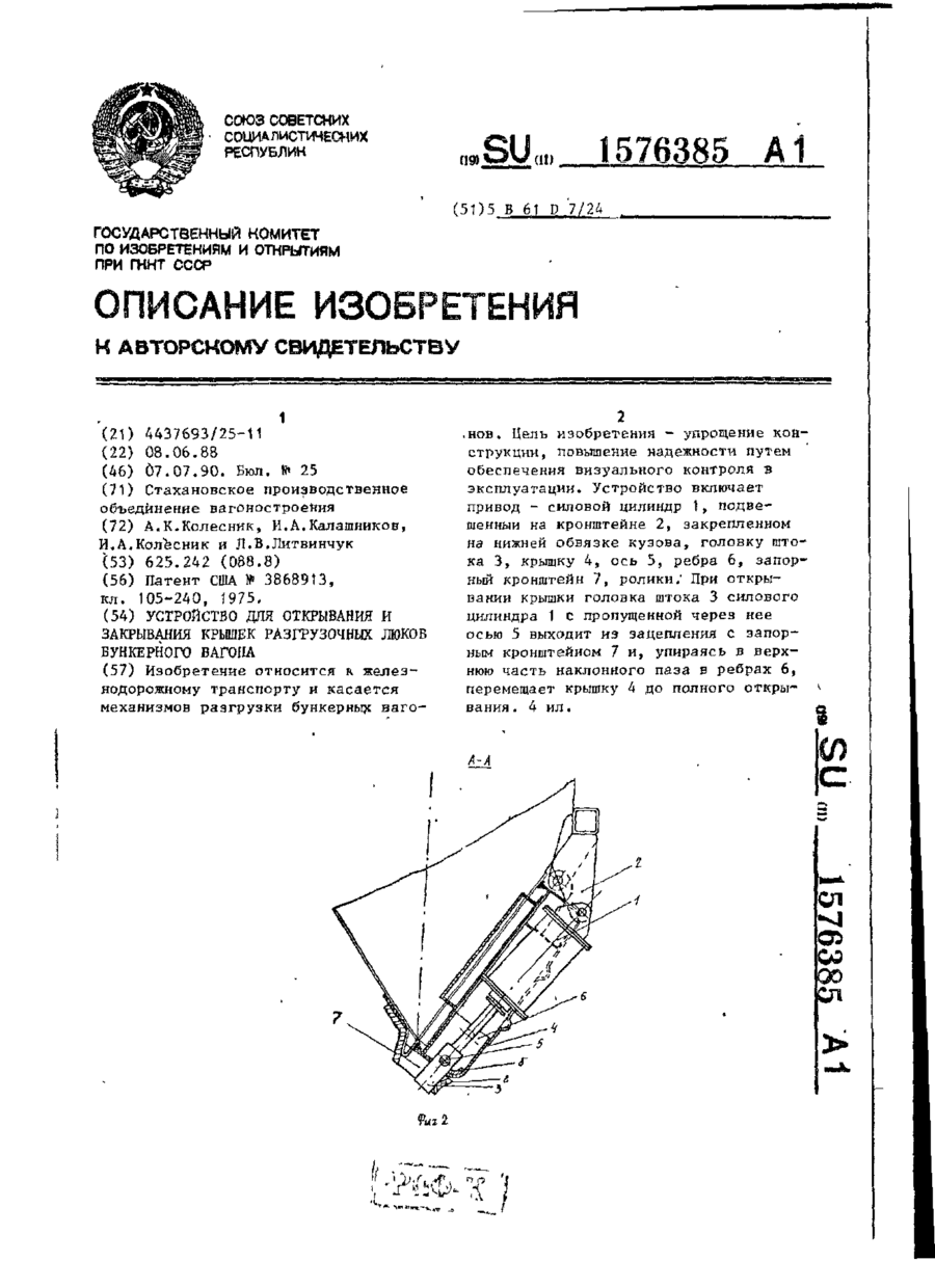
Устройство для открывания и закрывания крышек разгрузочных люков бункерного вагона, содержащее силовой циливдр привода для взаимодействия со средней частью крышки, отличающееся тем, что, с целью упрощения конструкции, повышения надежности путем обеспечения визуального контроля в эксплуатации, каждый силовой цилиндр шарнирно закреплен на нижней обвязке кузова с наружной стороны крышки, причем на его штоке посредством оси закреплена...
Пристрій для відкривання та закривання кришок розвантажувальних люків бункерного вагону
Номер патенту: 2625
Опубліковано: 26.12.1994
Автори: Чашкин Віктор Георгійович, Дяченко Микола Сергійович, Колесник Алім Кирилович, Ребенок Анатолій Георгійович, Трубачев Юрій Олексійович, Дровосеков Василь Іванович, Олефір Валентина Павлівна
МПК: B61D 7/26
Мітки: відкривання, вагону, бункерного, люків, розвантажувальних, закривання, пристрій, кришок
Формула / Реферат:
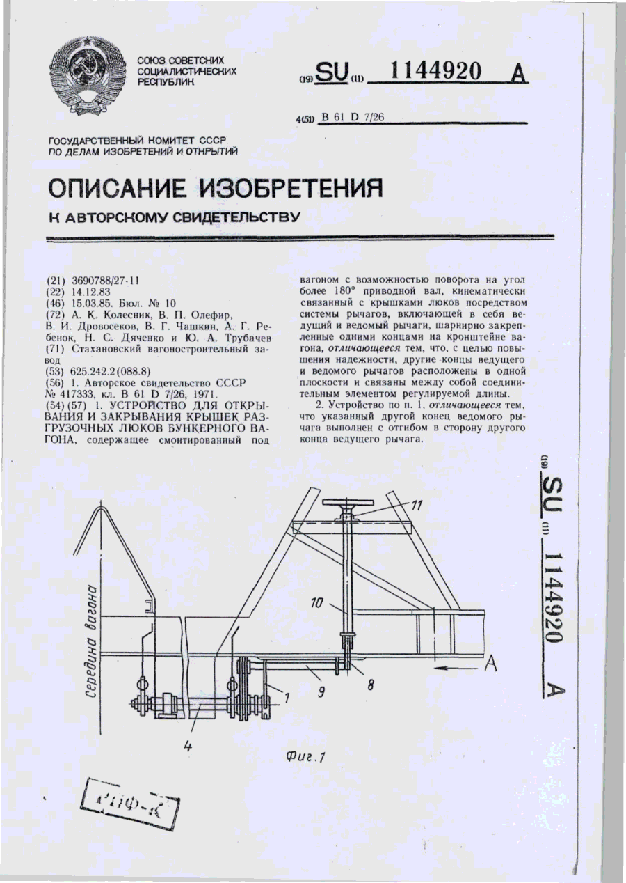
1. Устройство для открывания и закрывания крышек разгрузочных люков бункерного вагона, содержащее смонтированный под вагоном с возможностью поворота на угол более 180° приводной вал, кинематически связанный с крышками люков посредством системы рычагов, включающей в себя ведущий и ведомый рычаги, шарнирно закрепленные одними концами на кронштейне вагона, отличающееся тем, что, с целью повышения надежности, другие концы ведущего и ведомого...
Пристрій для відкривання та закривання кришок розвантажувальних люків бункерного вагону
Номер патенту: 1968
Опубліковано: 20.12.1994
Автори: Нога Григорій Миколайович, Колесник Алім Кирилович, Кульганек Генадій Йосипович, Оришак Олег Константинович, Литвинчук Леонід Володимирович
МПК: B61D 7/28
Мітки: бункерного, люків, пристрій, відкривання, кришок, закривання, розвантажувальних, вагону
Формула / Реферат:
Устройство для открывания и закрывания крышек разгрузочных люков бункерного вагона, содержащее смонтированные под вагоном связанный кинематически с крышками люков приводной вал и силовой цилиндр привода, соединенные между собой посредством зубчатого сектора, установленного на оси с возможностью зацепления с закрепленной на валу шестерней, и механизм блокировки вала, состоящий из поворотного в вертикальной плоскости сектора, смонтированного с...
Пристрій управління відкриванням та закриванням кришок розвантажувальних люків бункерного вагону
Номер патенту: 1967
Опубліковано: 20.12.1994
Автори: Борисов Рудольф Андрійович, Жданов Віктор Якович
МПК: B61D 7/28
Мітки: вагону, управління, відкриванням, бункерного, закриванням, люків, пристрій, розвантажувальних, кришок
Формула / Реферат:
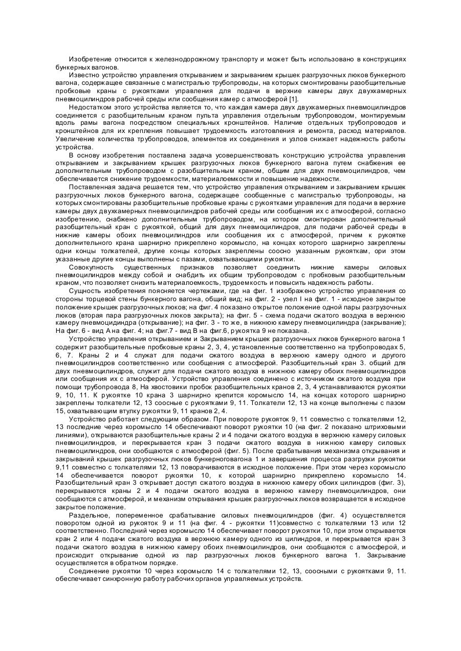
Устройство управления открыванием и закрывание крышек разгрузочных люков бункерного вагона, содержащее сообщенные с магистралью трубопроводы, на которых смонтированы разобщительные пробковые краны с рукоятками управления для подачи в верхние камеры двух двухкамерных пневмоцилиндров рабочей среды или сообщения их с атмосферой, отличающееся тем, что оно снабжено дополнительным трубопроводом, на котором смонтирован дополнительный разобщительный...
Механізм блокування штоків пневмоприводу кришок люків бункерного вагону
Номер патенту: 1873
Опубліковано: 20.12.1994
Автори: Биков Леонід Олександрович, Борисов Рудольф Андрійович
МПК: B61D 7/28
Мітки: блокування, механізм, люків, пневмоприводу, штоків, кришок, бункерного, вагону
Формула / Реферат:
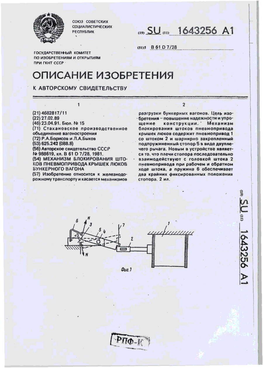
Механизм блокирования штоков пневмопривода крышек люков бункерного вагона, содержащий шарнирно закрепленный на раме вагона стопор, выполненный в виде двуплечего рычага, одно плечо которого связано с одним концом упругого элемента, отличающийся тем, что, с целью повышения надежности и упрощения конструкции, другой конец упругого элемента закреплен на кронштейне, который установлен на раме вагона, а другое плечо стопора смонтировано с...
Попередній патент: Композиція, яка фотополімерізується
Наступний патент: Розпушувач
Випадковий патент: Упаковка для сипучих продуктів одноразового заварювання