Пристрій для нагрівання і вивантаження в’язкої рідини із ємності
Формула / Реферат
1. Устройство для нагрева и выгрузки вязкой жидкости из емкости, содержащее промежуточную ёмкость для перелива жидкости из выгружаемой ёмкости через верхний люк в приёмную ёмкость, ресивер с нагревателем и системой клапанов для регулировки подачи и выпуска воздуха и жидкости, рассеиватель для обмывания стен внутри ёмкости и компрессор, отличающееся тем, что оно снабжено заборно-распределительным воздухонасосом, выполненным из корпуса с чехлом, заборной трубы с отверстиями, жёстко укрепленной в верхней части корпуса, состоящей из двух коаксиально установленных труб, одна из которых выполнена в виде установленного вверх дном стакана, и имеющих возможность перемещаться по ней вверх-вниз поршня и двойного конусообразного клапана с поплавковым клапаном, связанных через пружины, при этом в нижней части корпуса диаметрально расположены изогнутые перемычки с перегородочной сеткой, а верхний люк выгружаемой ёмкости снабжён крышкой.
2. Устройство по п. 1, отличающееся тем, что оно снабжено вакуумной ёмкостью для чистой выгрузки продукта из выгружаемой ёмкости.
Текст
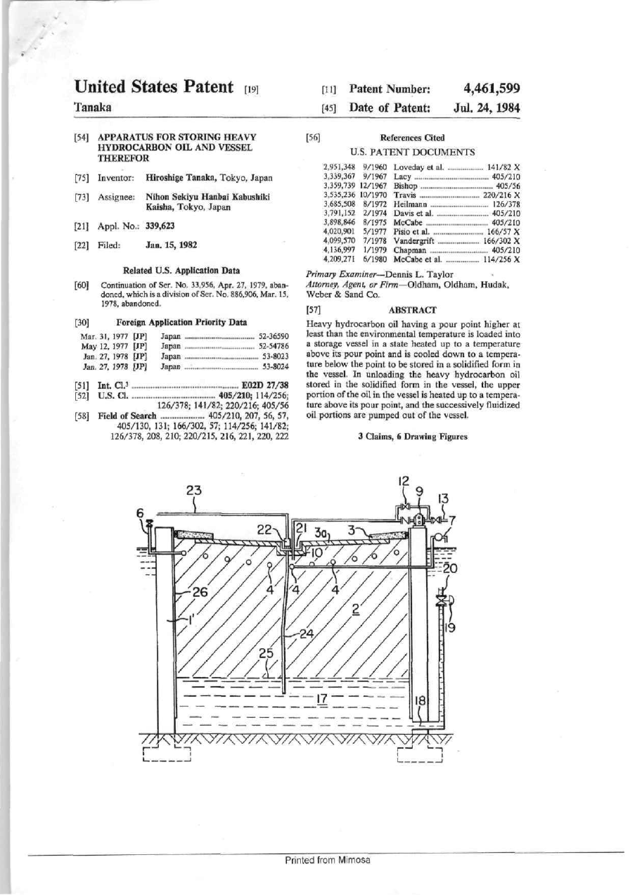
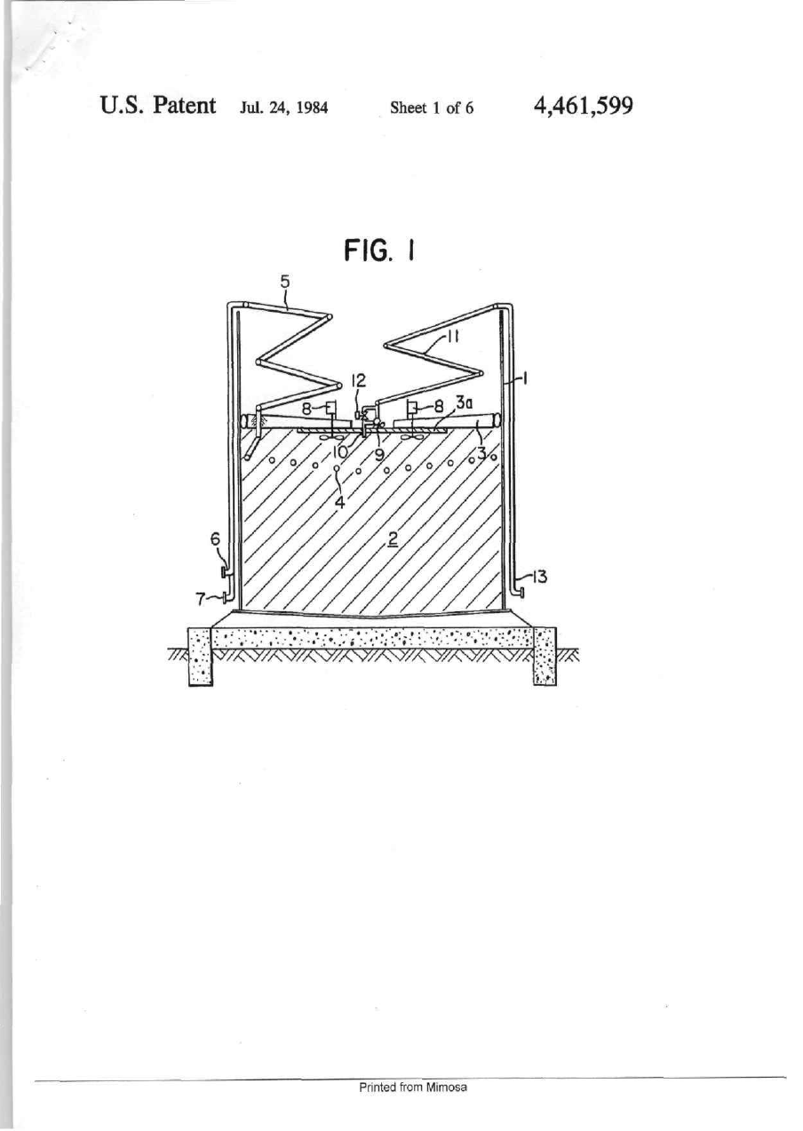
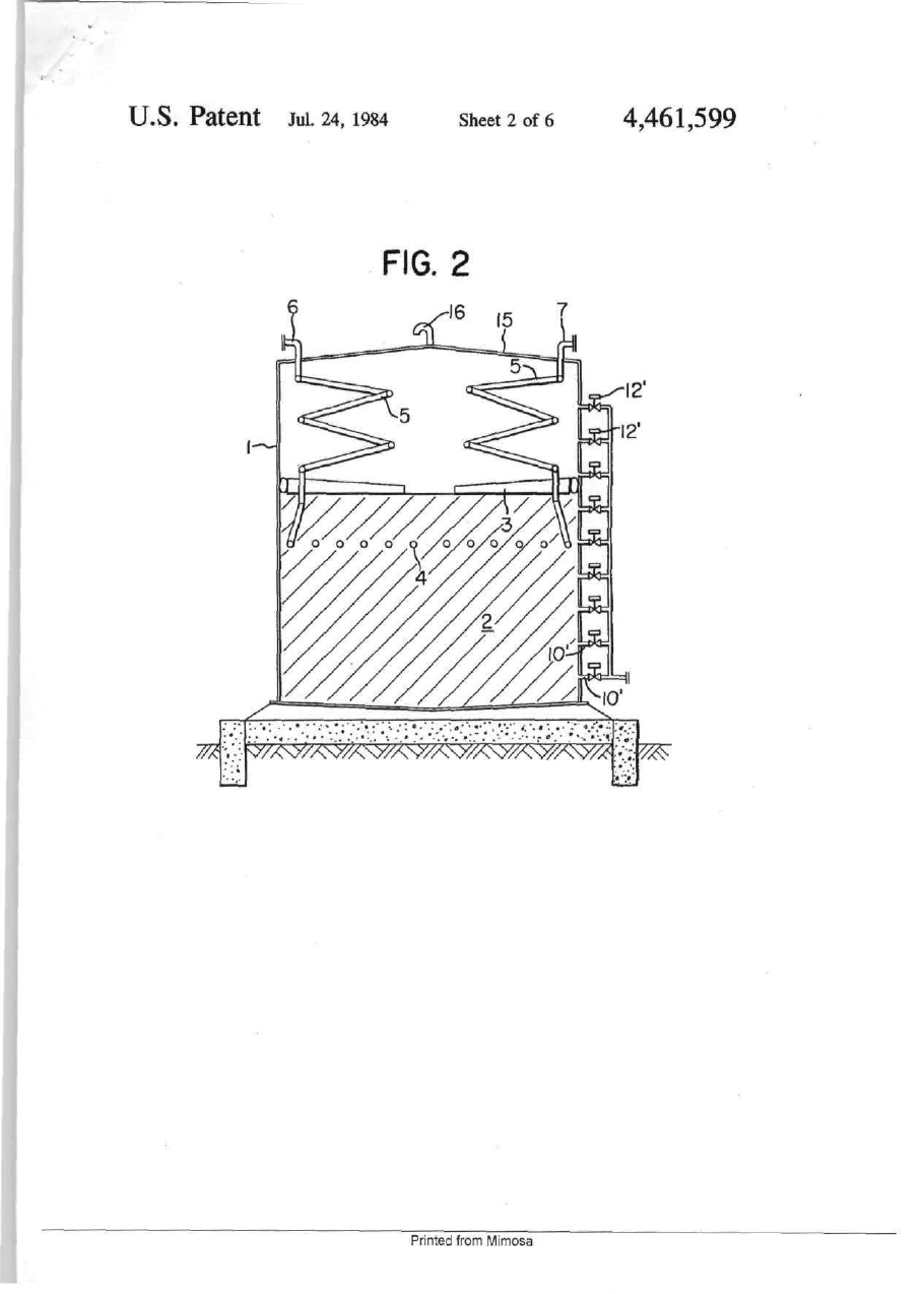
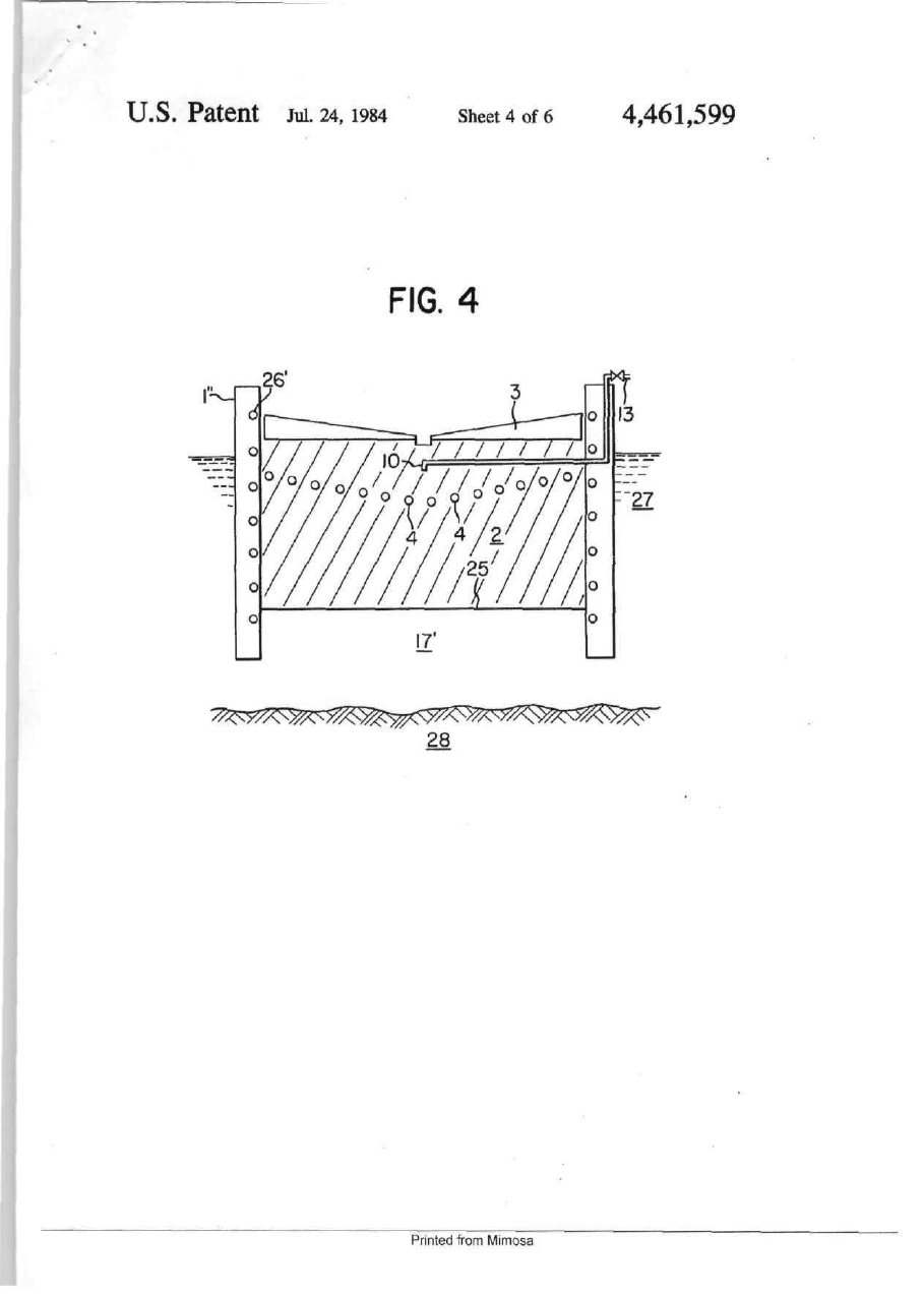
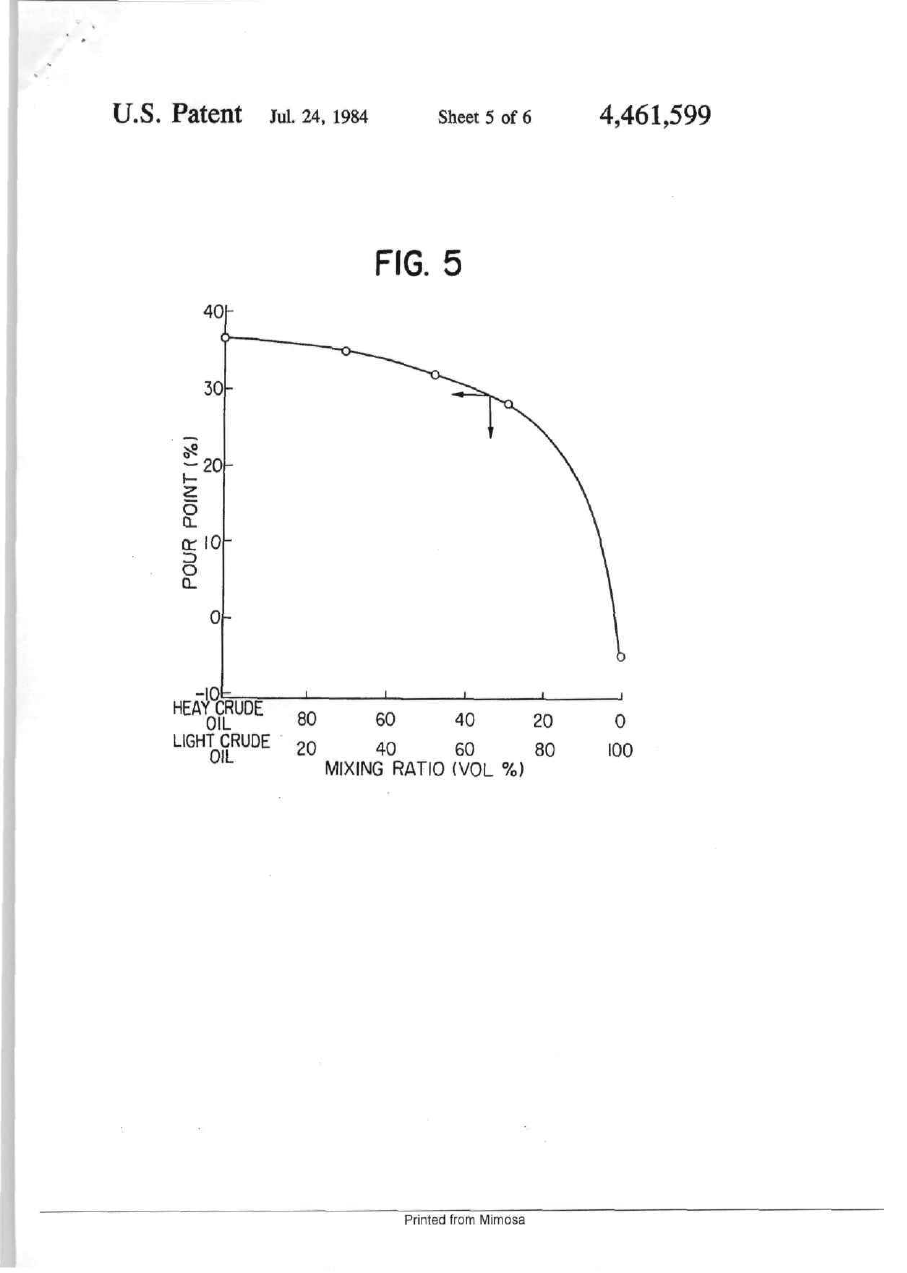
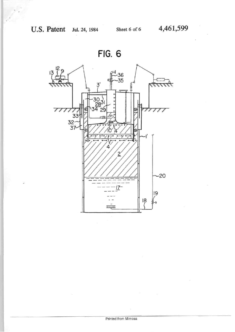
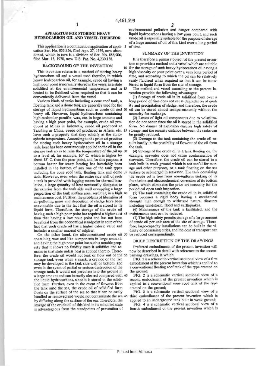
United States Patent [щ [II] Patent Number: Tanaka [45] [54] APPARATUS FOR STORING HEAVY HYDROCARBON O I L AND VESSEL THEREFOR [56] Inventor [73] Assignee Nihon Sekiyu Hanbai Kabushiki Kaisha, Tokyo, Japan [21] Appl N o 339,623 [22] Filed J a n . 15,1982 Related U.S. Application Data Mar May Jan Jan [51] [52] [58] Continuation of Ser No 33,956 Apr 27, 1979 aban doned, which IS a division of Ser No 886,906, Mar 15, 1978, abandoned Foreign Application Priority Data 31, 1977 12, 1977 27, 1978 27, I97S Int. a . 3 U.S. a . [JP] [JP] [JP] [JP] Japan Japan Japan Japan . 52-36590 52-54786 53-8023 53-8024 . References Cited 2,951,348 3 339,367 3,359,739 3 535,236 3,685,508 3,791,152 3,898 846 4,020,901 4,099,570 4,136,997 4,209,271 Hiroshige Tanaka, Tokyo, Japan [30] Jul. 24,1984 и S PATENT DOCUMENTS [75] [60] Date of Patent: 4,461,599 E02D 27/38 405/210; 114/256, 126/378, 141/82, 220/216, 405/56 Field of Search 405/210, 207, 56, 57, 405/130, 131, 166/302, 57, 114/256, 141/82, 126/378, 208, 210, 220/215. 216, 221, 220, 222 9/1960 9/1967 12/1967 10/1970 8/1972 2/і974 8/1975 5/1977 7/1978 1/1979 6/1980 Loveday et al Lacy Bishop Travis Heilmann Davis et al McCabe Pisio ct al Vandergnft Chapman McCabe et al 141/82 X 405/210 405/56 220/216 X 126/378 405/210 405/210 166/57 X 166/302 X 405/210 114/256 X Primary Exatnmer—Denms L Taylor Attorney, Agent, or Firm—Oldham, Oldham, Hudak, Weber & Sand Co [57] ABSTRACT Heavy hydrocarbon oil having a pour point higher at least than the environmental temperature is loaded into a storage vessel in a state heated up to a temperature above its pour point and is cooled down to a tempera ture below the point to be stored in a solidified form in the vessel In unloading the heavy hydrocarbon oil stored in the solidified form in the vessel, the upper portion of the oil m the vessel is healed up to a tempera ture above Its pour point, and the successively fluidized oil portions are pumped out of the vessel 3 Claims, 6 Drawing Figures //W'VyA\y/A'/A\Y 7 Printed from Mimosa A U . S . Patent Jul. 24, 1984 Sheet 1 of 6 FIG. I Printed from Mimosa 4,461,599 U.S. Patent Jul. 24, 1984 Sheet 2 of 6 FIG. 2 16 15 Printed from Mimosa T 4,461,599 VU.S. Patent Jul. 24, 1984 Sheet 3 of 6 FIG. 3 Printed from Mimosa 4,461,599 U.S. Patent Jul. 24, 1984 Sheet 4 O 6 f FIG. 4 28 Pnntedfrom Mimosa 4,461,599 U.S. Patent Jul. 24, 1984 4,461,599 Sheet 5 of 6 FIG. 5 -lOb HEAY CRUDE OIL LIGHT CRUDE OIL 80 20 60 40 20 40 60 80 MIXING RATIO (VOL %) Printed from Mimosa 0 100 U.S. Patent Jul. 24, 1984 Sheet 6 of 6 4,461,599 FIG. 6 '2Q 13 ( ^ ЧХХХХХ ^T/ /// Printed from Mimosa . 4,461,599 environmental pollution and danger compared with liquid hydrocarbons having a low pour point, and such crude oil is especially suitable for the purpose of storage of a huge amount of oil of this kind over a long period This application is a continuation application of appli- 5 of time, cation Ser. No. 033,956, filed Apr. 27, 1979, now aban doned, which in turn is a division of Ser. No. 886.906, SUMMARY OF THE INVENTION filed Mar. 15, 1978, now U.S. Pat. No. 4,230,138. It is therefore a primary object of the present invenDA/-'v/-Dr\nxTT-» r\n T-uc іхт\/'Г7іч.і'гтгчм tion to provide a method and a vessel which are suitable BACKGROUND OF THE INVENTION IA г .i, . e v. i. ». j L І t. • 10 for the storage of such heavy hydrocarbon oil having a This invention relates to a method of storing heavy high viscosity or pour point over a very long period of hydrocarbon oil and a vessel used therefor, in which time, and according to which the oil can be relatively heavy hydrocarbon oil, for example, crude oil having a easily fluidized when required so that it can be transhigh pour point is normally stored in the vessel in a state ferred in liquid form from the site of storage, solidified at the environmental temperature and is 15 The method and vessel according to the present inheated to be fluidized when required so that it can be vention provide the following advantages: conveniently delivered from the vessel. (1) Storage of crude oil in its solidified form over a Various kinds of tanks including a cone roof tank, a long period of time does not cause degradation of qualfloating tank and a dome tank are generally used for the ity and precipitation of sludge, and therefore, the crude storage of liquid hydrocarbons such as crude oil and 20 oil can be stored almost semipermanently without the heavy oil. However, liquid hydrocarbons containing necessity for exchange. high-molecular paraffin, wax, etc. in large amounts and (2) Losses of light oil components due to volatilizahaving a high pour point, for example, crude oil protion do not occur since the oil is stored in the solidified duced at Minas in Indonesia, crude oil produced at form. No danger of explosion ensures high safety of Taiching in China, crude oiJ produced m Africa, etc. 25 storage, and the security distance between the tanks can have such a property that they solidify at the atmobe greatly reduced. spheric temperature. According to the prior art practice (3) Damage to the tank containing the crude oil refor storing such heavy hydrocarbon oil in a storage suits hardly in the possibility of fiowout of the oil from tank, heat has been continuously applied to the oil in the the tank. storage tank so as to raise the temperature of the oil up 30 (4) Storage of the crude oil in a tank floating on, for to a level of, for example, 60° C. which is higher by example, seawater does not cause contamination of about 15° С than the pour point, and for this purpose, a seawater. Therefore, the crude oil can be stored in a bottom heater for steam heating has invariably been tank built in weak ground which is not useful for storinstalled in the bottom of any one of the tank types age and other purposes, or a tank floating on the sea including the cone roof tank, floating tank and dome 35 surface or submerged in seawater. The tank containing tank. However, even when the entire side wall of such the crude oil is free from non-uniform sinking of its a tank is provided with lagging means for thermal insufoundation and electrochemical corrosion of its bottom lation, a large quantity of heat necessarily dissipates to plates, which eliminates the prior art necessity for the the exterior from the tank side wall occupying a large periodical open tank inspection. proportion of the tank surface area, resulting in a high 40 (5) The tank containing the crude oil in its solidified maintenance cost. Further, the problems of liberation of form becomes a rigid body having a mechanical air-polluting gases and deposition of sludge have been strength high enough to withstand natural disasters unavoidable due to the fact that the oil is stored in its including windstorm, flood and earthquakes, liquid form. Therefore, the storage of the crude oil (6) Maintenance of the tank is facilitated, and the having such a high pour point has required a higher cost 45 maintenance cost can be reduced, than that having a low pour point and has not been (7) The high safety permits storage of a large amount beneficial from the economical standpoint in spite of the of crude oil per unit area of the site of storage. Therefact that such crude oil has a higher caloric value and fore, large-capacity installations can be built in the viincludes a smaller amount of sulphur. cinity of consuming cities, and the cost of transport can On the other hand, the aforementioned crude oil 50 be reduced correspondingly, containing wax and like components in large amounts DESCRIPTION OF THE DRAWINGS and having the high pour point has such a notable property that it shows no fluidity once it solidifies and rePreferred embodiments of the present invention will mains in that state unless heat is applied thereto. Therenow be described in detail with reference to the accomfore, the crude oil would not leak or flow out of the 55 panying drawings, is which: storage tank even when a crack, a crevice or the like FIG. 1 is a schematic vertical sectional view of a first may be developed in the tank side wall or bottom, and embodiment of the present invention which is applied to even in the event of partial or serious destruction of the a conventional floating roof tank of the type erected on storage tank, it would not percolate into the ground in the ground; a large amount and can be easily cleared compared with 60 FIG. 2 is a schematic vertical sectional view of a the liquid hydrocarbons, since it is stored in the solidisecond embodiment of the present invention which is fied form. Further, even in the event of fiowout from applied to a conventional cone roof tank of the type the tank onto the sea, the crude oil of solidified form erected on the ground; floats on the surface of the sea so that it can be easily FIG. 3 is a schematic vertical sectional view of a handled or removed and would not contaminate the sea 65 third embodiment of the present invention which is by diffusing along the surface of the sea. Therefore, the applied to an underground tank built in weak ground; storage of the crude oil of this kind in its solidified state FIG. 4 is a schematic vertical sectional view of a is advantageous from the standpoints of prevention of fourth embodiment of the present invention which is APPARATUS FOR STORING HEAVY HYDROCARBON OIL AND VESSEL THEREFOR Printed from Mimosa з '•''' 599 4 apphed to a sea-borne tank moored to the sea bottom tween the floating roof 3 and the top heater 4. The and floating on the sea surface; crude oil portion rendered to possess sufficient fluidity FIG, 5 is a graph showing the variation of the pour is pumped out by the pump 9 into the conduit 13 point oflight crude oil when heavy crude oil is mixed in through the nozzle 10 and expansible pipe U. .As the the light crude oil; and 5 surface level of the crude oil goes down, the Hoating roof 3 moves downward so that the top heater 4 applies FIG. б is a schematic vertical sectional view of a now heat to the further lower portion of the crude oil modification of the third embodiment, in which the stored in the tank. When, on the other hand, the pump outer periphery of the fioating roof of the underground 9 is not driven, and the valve 12 is opened to permit the tank is sealed with water. flow of fluidized crude oil into the tank from the nozzle DESCRIPTION OF THE PREFERRED '° 10, the surface level of the crude oil rises gradua/ly to EMBODIMENTS cause correspondmg upward movement of the oontoon-hke floating roof 3. Referring now to FIG. 1 showing a first embodiment of the present invention which is applied to a conven In a second embodiment shown in FIG. 2, the present tional floating roof tank of the type erected on the 15 invention is applied to a conventional cone roof tank. In ground, this tank has such a structure that its side wall FIG. 2, the same reference numerais are used to denote 1 is erected on a strong bottom foundation, and a pon the parts common to the first embodiment shown in toon-like floating roof 3 and a center cover sheet 3a FIG. 1. Referring to FIG 2, the reference numerals 15 disposed in the internal oil-storing space is afloat on the and 16 designate a cone roof tank top and its air vent surface of crude oil 2 stored in the tank. According to 20 respectively. In this second embodiment, a plurality of this first embodiment of the present invention, a top loading and unloading nozzle 10' are disposed along the heater 4 for steam heating ts fixed to the lower face of tank side wall 1 at a plurality of vertically spaced levels the floating roof 3 and has a heating area which covers and are each provided with a valve 12' This arrange substantially the entire area of the oil-storing space. ment eliminates (he expansible piping 31 and pump 9 This top heater 4 is connected by a pair of expansible 25 employed in the first embodiment. In this second em pipes 5 with a heating medium supply conduit б and a bodiment, therefore, the stored crude oil can be un heating medium discharge conduit 7. A nozzle 10 ex loaded from the tank by opening the valve 12' located at tends downward from the floating roof 3 in the space the level corresponding to the position of the top heater between the floating roof 3 and the top heater 4. This 4 which moves upward and downward with the float nozzle 10 IS provided for the purpose of loading and 30 ing roof 3 as the corresponding layer of the crude oil is unloading the crude oil into and from the tank and is fluidized. It is to be noted that the other features are connected with a crude oil conduit 13 through a valve entirely the same as those of the first embodiment. 12 and an expansible pipe 11. A pump 9 is fixed to the floating roof 3 and communicates with the nozzle 10 Further, although not specifically illustrated as an and pipe 11 so that the crude oil can be pumped out of 35 embodiment, it is apparent that the present invention is the tank when the valve 12 is closed. The reference equally effectively applicable to a conventional dome numeral 8 designates propeller type mixers. lank by providing a floating body or floating roof hav ing a top heater similar to that described above. It will Heavy crude oil having a high pour point is heated up be thus seen that the present invention is easily advanta to a temperature above its pour point and is loaded through the conduit 13 into the tank of such a structure. 40 geously applicable to any one of existing tanks by merely making a partial reconstruction thereof This crude oil is, for example, that produced at JatibaIn a third embodiment shown in FIG. 3, the preseni rang (having a pour point of -ь42.5° С), that produced invention is applied to an underground tank built in at Cinta (having a pour point of -Н42.5° С), that pro weak ground as in a reclaimed land. duced at Lirik (having a pour point of 4-40.0' C), that Referring to FIG. 3, the reference numeral 1' desig produced at Tanjung {having a pour point of 4-40.0° 45 nates an underground side wall of circular shape built C), that produced at Minas (having a pour point of up in a cavity formed by excavating ground to a suitable 4-37.5° C ) , or that produced at Pematang (having a depth to define a crude oil-storing space therein. The pour point of 4-37,5° C), all these oil fields being lo earth removed by the excavation is advantageously cated in Indonesia. The crude oil may be that produced at Bahia (having a pour point of 4-35 0' C.) in Brazil, 50 piled up along the outer periphery of the top end of the side wall 1' to increase or substantially double the tank that produced at Taiching (having a pour point of 4- 32.5° C.) Ш China, or that produced at Cabina (having capacity. Even when the tank side wall has thus a height which may be about two times the depth of the a pour point of +25.0° C.) in Africa. The crude oil is cavity measured from the original ground level, the stored in the storing space beneath the floating roof 3 as shown in FIG. 1 and is allowed to cool down to a tern- 55 ground portion forming the lank bottom will suffi ciently withstand the load to be borne by the tank m perature below its pour point. In such a state, therefore, view of the fact that the specific gravity of the crude oil neither volatjlizalion of light oil components nor pre stored in the tank is only about 0.85. The shape of the cipitation of sludge occurs, and the crude oil can be side wall 1' of the tank thus constructed is not limited to very stably and safely stored in its solidified state with out the possibility of flowout and other troubles even in 60 the circular shape and may be a polygonal shape or more generally a square shape. the event of an earthquake or any other natural disas ters. A floating roof 3 like that used in the aforementioned embodiments and having a center cover sheet 3a is When it is desired to unload the crude oil stored in provided in the internal space of the side wall 1' Since the solidified form, the top heater 4 is energised to start to heat the upper porUon of the crude oil stored in the 65 this floating roof 3 does not make appreciable vertical movement within the tank, it may be substantially fixed tank. After the starting of heating operation by the top to the top of the side wall Г. A simple roof may be used heater 4, the propeller type mixers 8 are driven to pro ;n place of the floating roof 3. A lop heater 4 is shown mote convection of the fluidized crude oil portion be Printed from Mimosa il,599 fixed to the side wall 1', but it may be fixed to the float ing roof 3 as in the aforementioned embodiment. The reference numeral 10 designates a crude oil load ing and unloading nozzle, and this nozzle 10 communi cates with a crude oil conduit 13 through a pipe, a valve 12 and a pump 9. The crude oil 2 loaded into the tank through this nozzle 10 is allowed to cool down unfil it takes its solidified state as described hereinbefore. The lower portion of the crude oil stored in the solidified form in the tank borders on a layer 17 of seawater through a boundary 25. This underlying seawater layer 17 communicates with the open sea (not shown) through a lower conduit 18, a control valve 19 and an upper conduit 20, or with a water level control device (not shown). It is apparent that the bottom of this under ground tank need not be closed when it communicates with the open sea. A rainwater pool 21 is provided at the center of the floating roof 3 and communicates with the exterior through a drain pump 22 and a drain conduit 23 con nected thereto or with the underlying seawater layer 17 through a drain conduit 24. A steam piping or a planar heat generator layer 26 is disposed on the inside face of the tank side wall 1' so as to heat the stored crude oil up to a temperature above its pour point. When so required, in addition to or in place of such a heating means, a coating of material such as teflon or epoxy resin may be provided on the inside face of the tank side wall 1'. The provision of the coat ing of such material is effective in that the material has a low coefficient of friction and possesses such a prop erty that it is hardly wetted by the crude oil. when now it is desired to store crude oil in this tank, seawater in the vicinity of the top heater 4 is first heated by the top heater 4 up to a temperature higher by more than 10° C. than the pour point of the crude oil, and then, the crude oil heated up to approximately the same temperature is fed into the zone directly beneath the floating roof 3 through the conduit 13, valve 12 and nozzle 10. Although not shown, the crude oil is preferably forced out of the tip of the nozzle 10 in a horizontal direction in this case so as to prevent the crude oil from mixing with seawater. The crude oil is fed into the tank while displacing the seawater in the lower portion of the tank through the lower seawater discharge conduit 18 until its surface level is stabihzed at the position balanced with the head of seawater. The relation be tween the crude oil level and the seawater level in the tank is given by Ho=i d/do)Я, where d is the specific gravity of crude oil. do is the specific gravity of seawater. Ho is the height of crude oil between the oil-seawater boundary 25 and the crude oil level in the tank, and H is the height of seawa ter between the oil-seawater boundary 25 and the open sea level- Since do
ДивитисяДодаткова інформація
Автори англійськоюMusiichuk Volodymyr Volodymyrovych
Автори російськоюМусийчук Владимир Владимирович
МПК / Мітки
МПК: B65D 88/74, B65G 69/20
Мітки: рідини, вивантаження, в'язкої, ємності, пристрій, нагрівання
Код посилання
<a href="https://ua.patents.su/12-44750-pristrijj-dlya-nagrivannya-i-vivantazhennya-vyazko-ridini-iz-ehmnosti.html" target="_blank" rel="follow" title="База патентів України">Пристрій для нагрівання і вивантаження в’язкої рідини із ємності</a>
Пристрій для нагрівання рідини
Номер патенту: 522
Опубліковано: 15.09.2000
Автори: Лисиця Михайло Ілліч, Лисиця Олена Іллівна, Лисиця Ілля Захарович, Лисиця Ніна Олександрівна
МПК: A47J 36/24
Мітки: пристрій, нагрівання, рідини
Формула / Реферат:
Пристрій для нагрівання рідини, що містить герметичну посудину для рідини, джерело нагрівання, та іскороутворювач, який відрізняється тим, що джерело нагрівання виконано у вигляді розміщеної в корпусі ємкості для скрапленого газу, сполучено) з газовим пальником, корпус має вікна, розташовані у нижній його частині, а герметичну посудину прикріплено до корпусу та встановлено над пальником.
Пристрій для нагрівання рідини
Номер патенту: 22003
Опубліковано: 30.04.1998
Автори: Іванов Анатолій Яковлевич, Ткаченко Анатолій Володимирович, Осаул Олександр Іванович, Потапов Юрій Семенович, Хлопков Леонід Пімонович
МПК: F25B 29/00
Мітки: нагрівання, рідини, пристрій
Формула / Реферат:
1. Устройство для нагрева жидкости, содержащее теплогенератор со входом и выходом, насос, подающий и обратный трубопроводы, инжекционный патрубок, соединенный со входом теплогенератора, содержащего последовательно соединенные ускоритель движения жидкости и трубчатую часть с тормозным устройством на выходе теплогенератора, с которым соединен обратный трубопровод, отличающееся тем, что инжекцнонный патрубок снабжен щелевой диафрагмой,...
Пристрій для нагрівання рідини
Номер патенту: 1056
Опубліковано: 17.09.2001
Автори: Зінченко Валерій Степанович, Сухоносов Віктор Іванович
МПК: F25B 29/00
Мітки: пристрій, нагрівання, рідини
Формула / Реферат:
1. Пристрій для нагрівання рідини, що має теплогенератор з вхідним і вихідним патрубками, який включає проточний бак, прискорювач руху рідини, під'єднаний на вхід до проточного бака, перепускний патрубок, який своїм виходом підключений до вихідного патрубка теплогенератора, циркуляційний насос, вихід з якого підключений до вхідного патрубка теплогенератора, а вхід - до вихідного патрубка теплогенератора, подавальний і зворотний трубопроводи...
Пристрій для індукційного нагрівання рідини в трубопроводі
Номер патенту: 24587
Опубліковано: 16.07.2001
Автори: Лаппа Олег Павлович, Єрьомін Володимир Петрович, Єрьомін Генадій Петрович
Мітки: рідини, нагрівання, трубопроводі, індукційного, пристрій
Формула / Реферат:
1. Устройство для индукционного нагрева жидкости в трубопроводе, включающее последовательно соединенные регулятор переменного тока, индукционный нагреватель, содержащий по меньшей мере одну индукционную обмотку с электротеплоизоляционной прокладкой, охватывающую цилиндрическую магнитопроводную емкость, имеющую связанные с трубопроводом входной и выходной патрубки, первый термодатчик, механически закрепленный на выходной магистрали...
Пристрій для нагрівання рідини та теплогенератор, що використовується в ньому
Номер патенту: 7205
Опубліковано: 30.06.1995
Автор: Потапов Юрій Семенович
МПК: F25B 29/00
Мітки: рідини, ньому, теплогенератор, використовується, нагрівання, пристрій
Формула / Реферат:
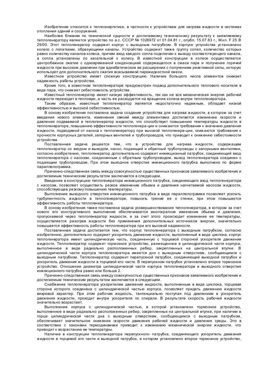
1. Устройство для нагрева жидкости, содержащее теплогенератор со входом и выходом, насос подающий и обратный трубопроводы с запорными вентилями, отличающееся тем, что дополнительно содержит инжекционный патрубок, соединяющий вход теплогенератора с насосом, соединенным с обратным трубопроводом, выход теплогенератора соединен с подающим трубопроводом.2. Устройство для нагрева жидкости по п. 1, отличающееся тем, что инжекционный...
Попередній патент: Фільтр- денітрифікатор
Наступний патент: Дистанційно програмована медична система вливання та спосіб її дистанційного програмування
Випадковий патент: Спосіб виробництва вареної ковбаси, збагаченої кальцієвмісною добавкою