Повнорушійний фронтальний навантажувач
Номер патенту: 35217
Опубліковано: 16.06.2003
Автори: Плютін Іван Іванович, Задєєв Евгеній Павлович, Черкасов Володимир Петрович, Приходько Володимир Іванович, Воронович Віктор Петрович, Баздирєв Володимир Дмитрович, Ільін Сергій Миколайович

Формула / Реферат
Повнорушійний фронтальний навантажувач, який містить самохідне з навантажувальним обладнанням пневмоколісне шасі, коливний міст з цапфами і опору з кронштейнів з підшипниками для цапф на рамі шасі, який відрізняється тим, що опора виконана з можливістю відокремлення від рами шасі і забезпечена знімними балками регульованої довжини, які з’єднують кронштейни опори між собою.
Текст
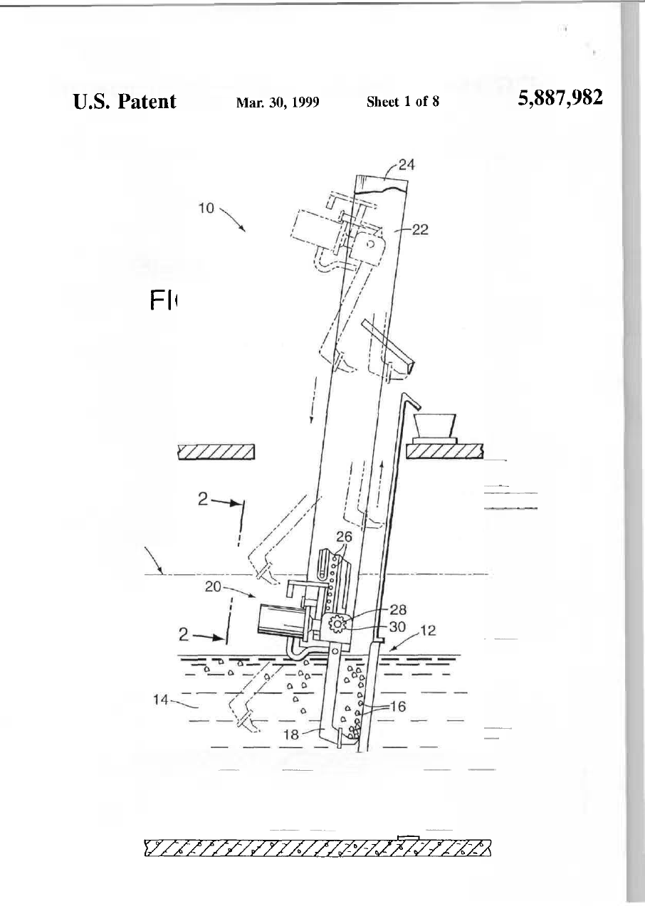
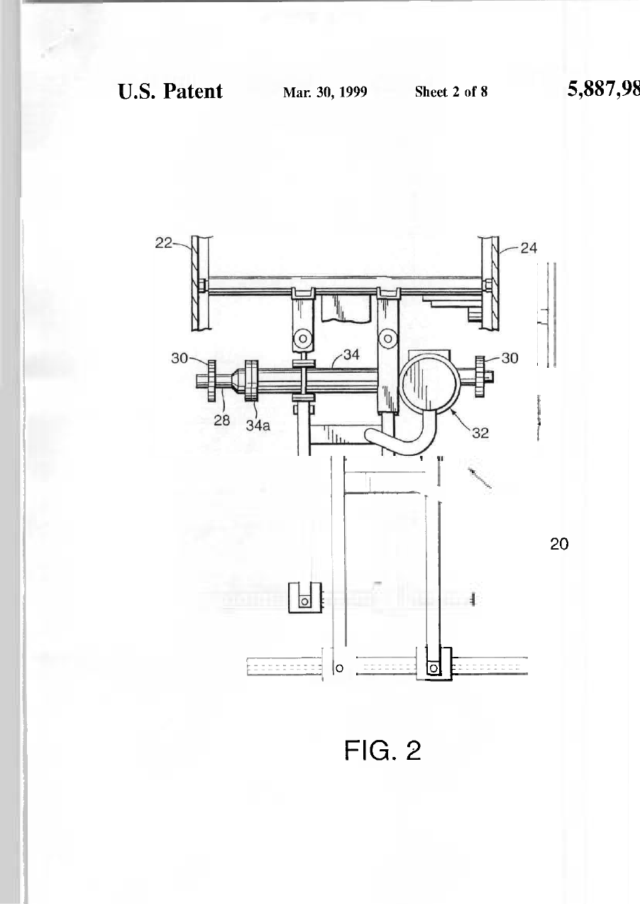
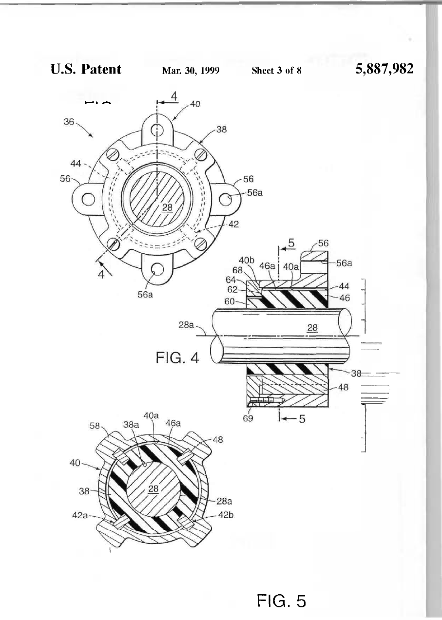
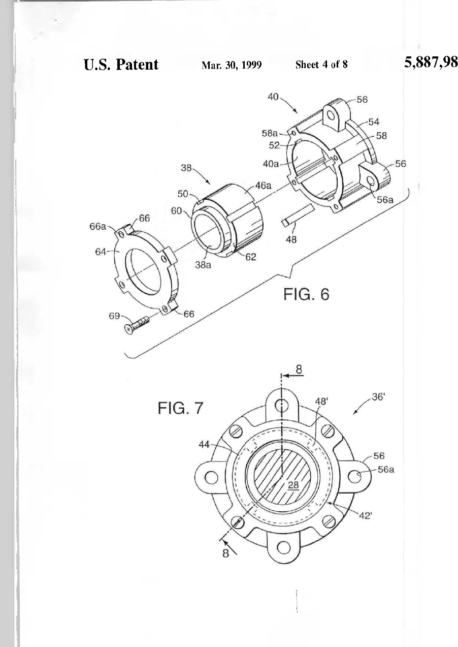
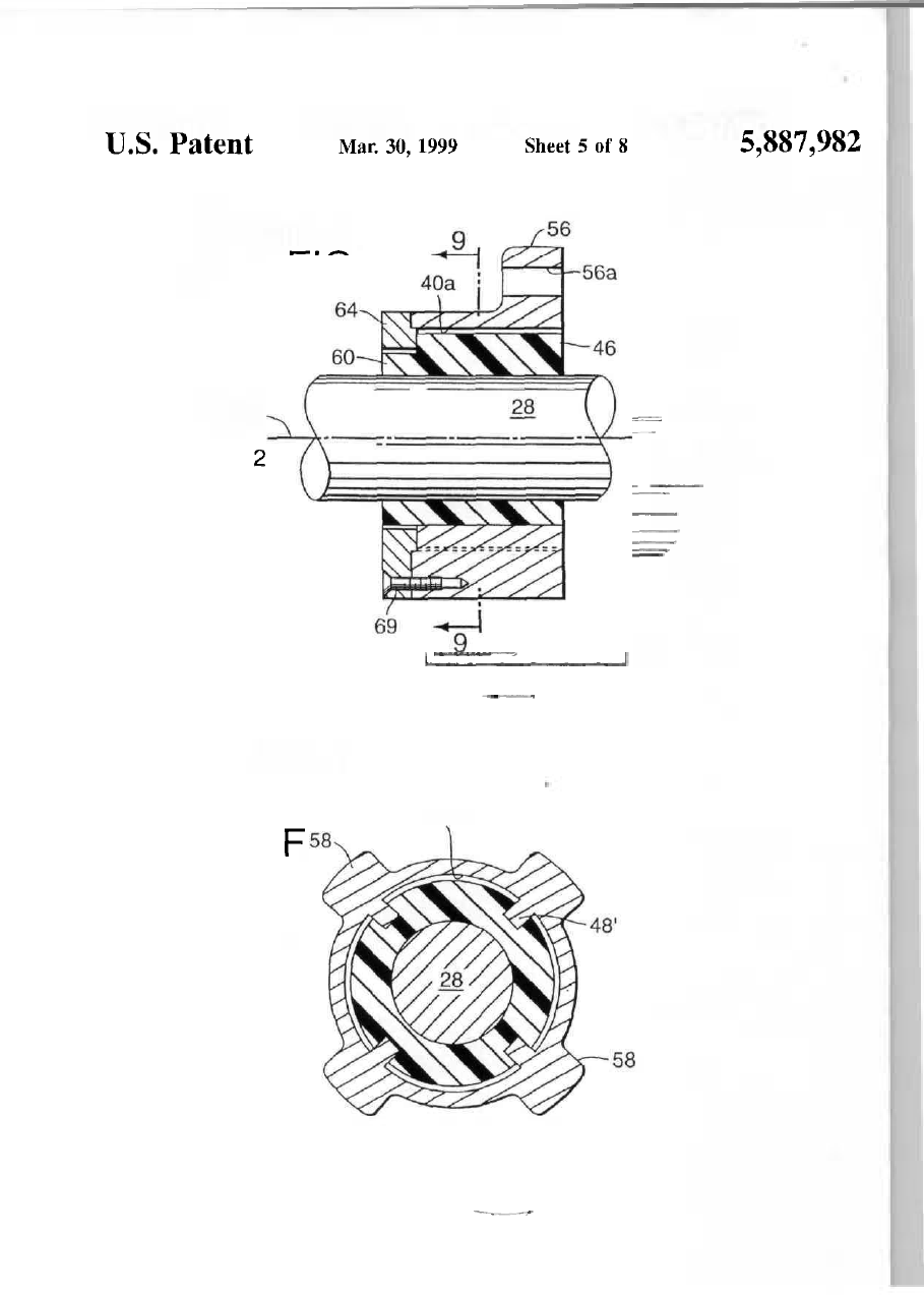
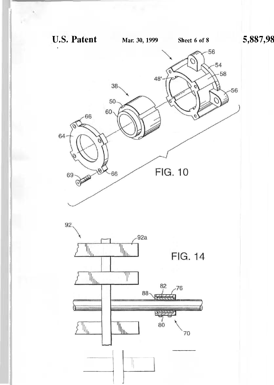
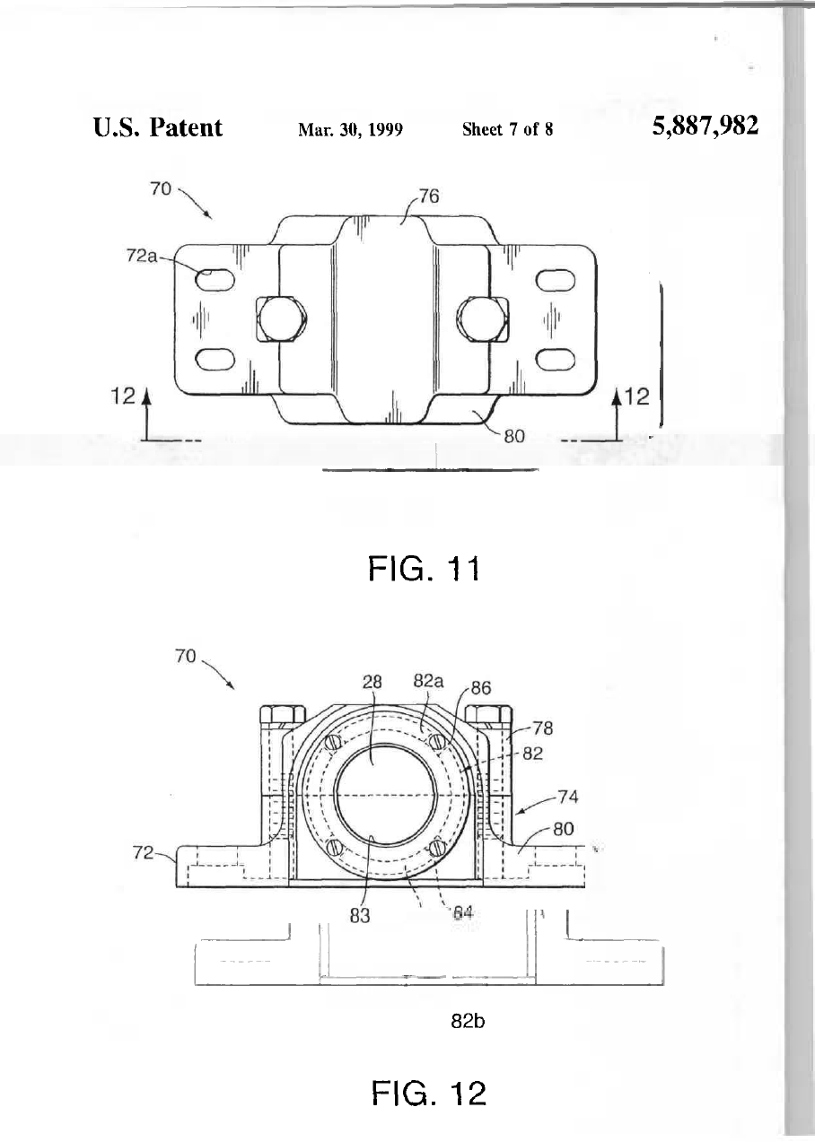
lllllllinnillllllllllll United States Patent [i9] US005887982A [11] Patent Number: Wilchcr [54] [45] Date of Patent: BEARING ASSEMBLY FOR USE WITH A SUBMERGED APPARATUS AND METHOD FOR PERFORMING MAINTENANCE THEREON 5,887,982 Mar. 3», 1999 Cooper Bearing Company. Cooper Split Roller Bearings— product description. Not Dated, 3 pages Primary Examiner—Thomas R Hannon Attorney, Agent, or Firm—Michael, Best & Friedrich [75] Inventor Stephen B. Wilcher, Harleysville, Pa. [57] [73] Assignee U.S. Filter Wastewater Group, Inc., Palm Desert, Caht [21] Appl No. 877,598 [22] Filed: [51] Int. Cl.^ The present beanng assembly is for use with a wastewater treatment apparatus which is driven by a dnve shaft, e g . cog rake bar screens, or water treatment apparatus, e g , paddle wheels in flocculation mixing tanks, and submerged, partially submerged or intermittently submerged in a liuid environment The beanng as.sembly includes a tubular mem ber keyed against rotation m a bearing housing with tht tubular member bore surfaces engaged against the drtvt shaft surfaces without rolling elements disposed therebc' tween thus eliminating the need for lubricators to supply the bearings With grease Accordingly, the present dry bearing assembly is not subject to failures caused b\ having tht grea-se in the bearingsflu.shedout by wastewater flows or bj submerging of the lubricator In addition, the keyed connec' tion provided between the housing and beanng member allows the bearing member to be slid out from the housing and rotated so as to present a ditterent section of the loat bearing surface below the slowly rotating honzontal shaf for taking the downward loads thereof providing an ea.sj method of performing maintenance on the beanng assembly Clearances provided between the housing and bearing mem ber facilitate this sliding of the beaiiiig membei uut trunt tht housing, provide flow paths to allow wastewater to flow oui from the beanng assembly, and allow tor the bearing memi ber when made from a pldstic material to expand radiallj) when exposed to varying temperature wastewater environ4 ments An alternative split construction pillow block beanng assembly is disclosed which allows the bearing membe: inner surfaces to be observed for any wear and to provide ar indication of the level ot wear on the primary load beannj surface of the lower half of the bearing member [52] [58] Jim. 17, 1997 F16C 3/00, F16C 23/02, F16C 33/66 U.S. CI 384/97, 384/247, 384/276, 384/295, 384/315 Field (»f Search 384/97, 247, 261, 384/263, 276, 278, 2У5, 297, 299, 315, 428, 434, 435, 906 References Cited [56] и S. PATENT DOCUMENTS 2.710,235 3,084,003 4,653,344 4,756,632 4,909,63У 5,246,573 5,618,107 6/1955 4/1963 3/1987 7/1988 J/199U 9/1993 4/1997 Olsen Matt et al Nelson Belanger Belanger Lodholz et ai Barlscli 384/263 384/278 384/295 X 384Д63 X 384/9U6 X 210/159 384/276 X OTHER PUBLICAnONS Polymer Corporation, Chemical Resistance Data, Not Dated, 4 pages Reading, PA Polymer Corporation, Nylatron GSM Blue Nylon Machining Stock—product brochure, 1995, 6 pages Reading PA Lmk-Belt/FMC, Series B22400 and B22500-Sphencal roller Bearings and Roller Bearing Umls,—product descrip tion, Not Dated, 3 pages. 40a ABSTRACT 18 Claims, 8 Drawing Sheets 46a U.S. Patent Mar. 30, 1999 Sheet 1 of 8 FIG. 1 14A УУ///УУУУУУАУУУУУУУУ7УУУУУЛ 5,887,982 U.S. Patent Mar. 30, 1999 Sheet 2 of 8 5,887,982 20 й о FIG. 2 U.S. Patent Mar. 30, 1999 Sheet 3 of 8 FIG. 3 FIG. 5 5,887,982 U.S. Patent Mar. 30, 1999 Sheet 4 of 8 5,887,982 U.S. Patent Mar. 30, 1999 Sheet 5 of 8 FIG. 8 28a FIG. 9 40a 5,887,982 U.S. Patent Mar, 30, 1999 Sheet 6 of 8 40 5,887,982 U.S. Patent Mar. 30,1999 Sheet 7 ot 8 FIG. 11 82b FIG. 12 5,887,982 U.S. Patent Mar. 30,1999 Sheet 8 of 8 5,887,982І О LL 5,887,982 1 2 B E A R I N G ASSEMBLY F O R USE W I T H A S U B M E R G E D APPARATUS AND M E T H O D lOR P E R F O R M I N G M A I N T E N A N C E THEREON beanngs The drive shaft has cog wheels on either end thereof for cooperating with cog pins disposed m substan tially vertical side frame members mounted over the screen upstream therefrom The entire гаїїе and drive assembly moves up and down the side frame members as the drive shaft rotates during a cleaning cycle tor raking ot the bar screen Willie cog take bai scieens piovide substantial advantages in terms of manpower efhcicncy over the manual cleaning methods previously employed, they can also encounter mamtenance problems One parhcular problem faced with cog rake bar screens is the failure ot the bearings utilized with the mam drive shaft For supportmi; the drive shaft for rotation, conventional melal contacting roller clement bear mg units are provided on cither end of the shaft One ot the pnmary benefits and features ot the cog rake bar screen enabhng significant commercial success in recent years is that there are typically no moving parts located below the water surface, and the main drive and rake support assembly including the drive shaft and torque tube with (he convenhonal hearings were always located above the operating floor so that these parts were readily accessible for mainte nance purposes However, many recent applications require that cog rake bar screens be installed in multiple story mstaflations or remote pumping stations, such as near nvers which tend to flood When uhhzed ш these tvpes of installations, the cog rake bar screen drive carriage has the potenhal to be submerged during its cleanmg cycle such as when the rakes travel towards the bottom of the screen As the beanngs require grease lubrication and thus the use ot spnngloaded automatic lubricators which can be mounted to the drive assembly, they experience significant problems when submerged in wastewater flows The harsh wastewater environment includes exposure to wide ranging water temperaliires from approximately 2S° Г to -5° С and exposure to a variety of difterenl corrosive chemicals that can be found in and added to wastewater It has been found that when the bearings are submerged, the flow of water or sewage tends to flush the grease from the beanngs, leading to rapid surface wear and corrosion and additional mainte nance requirements In addition, no current commercially available lubricators are made for fully submerged service AU these factors lead to repeated failures when the cog rake bar screen dnve carriage is utilized m applications where the dnve assembly is likely to be submerged in wastewater exposing the bcarmgs and lubricators therefor to the harsh wastewatei environment When the beanngs fail, the entire drive carnage must be removed from the frame of the cog rake bar screen and disassembled in order to replace the dnve shaft support bearings s FIELD OF THE INVENTION The invention relates to bearmg assembhtb and, more particularly, to a bearing assembly tor use with the drive shaft of a water treatment apparatus which can be operated with the beanng assembly submerged BACKGROUND OF THE INVENTION Municipal wastewater, or domestic sewage, is composed of water borne waste derived from household Uhes and light uidustry This includes human waste and wash waters as well as oiLs, greases, and animal and vegetable matter Heavier industrial sources, such аь breweries and pulp mills, typically have Ihejr own treatment or pretreatment plants because their waste generally would overload the usual municipal lacdity Domestic sewage can contain 1000 to 2000 parts per mUlion of solid materials with about half of the material being in solution and half in suspension or floating The contents of industrial waste vary tor different processes ot manufacture, and the percentage of solid material Ш sewage trom an industrial plant may be very small or inordmantly large Where storm rain water is to be led away through sewers, openmgs in the street gutters afford entrance to the sewers The same sewer may carry all three types of sewage, 1 e , domestic, industnal and storm, in a combined system Raw sewage from the sewer mams may containsticks, leaves, rags, paper, glass, sand, gnt, cinders and other objects, all of which are liable to clog or injure pumps In order to ensure salLsfactory operation of the pumps, such matenals must be removed before (he sewage is admitted to the pumps Large floating objects are usually removed by means ot racks or screens that consist of flat bars of iron or steel set a short distance apart and with the wide faces ot the bars parallel Since the purpose of instahing the screen or rack IS to remove the larger solids, the bars ot the screen are placed Y2 to 3 apart As stated above, these bar screens are used prim inly to remove from the sewage sticks, rags, or other matenals thai may clog pumps or may interfere with the operation of devices for treatment They are often used in conjunction with a grit chamber placed al either end of the chamber, but generally is at the inlet end The width and length ot the screen are such as may be necessary to provide for the expected maximum flow of sewage with the screen usually set with the bars sloping in the direction of the flow ol sewage jg 20 25 3,) 34 ao 44 50 Other places where conventional metal-to-metal contact Typicafly, bar screens must be cleaned on a frequent basis ing roller element bearings are not acceptable tor use Bar screens that are not equipped with an automatic cleaning because ot exposure to water requiring frequent mainte device require an attendant to rake off the screen whenever nance IS in flocculation mixmg tanks Chemicals are added enough material has accumulated on the screen to interfere 55 to the sewage as coagulanb to improve sedimentation with with the flow Hand raking of the screens IS an inefBcient use thorough miMng ot the coagulant chemical with the sewage ot time and manpower Accordingly automatic raking being desirable in order to obtain economy in chemical mechanisms have been developed for use with bar screens dosage Gentle mixing is also generahy necessary in order to which can be controlled by a liming device for executing obtain a Hoc, or coagulant, that is large enough to settle cleaning cycles at predetermined periods and/or based on 60 After the floe has been formed, provision must be made for predetermined operahng conditions and thus do not depend a quiescent penod, during which the floe can settle and carry on the presence or eftort of an attendant An autoraaUc down with it the suspended and etilloidal matter m the rakmg mechanism m a cog rake bar screen apparatus is sewage These conflicting requirements are best met by dLsclosed in и S Pat No 5,246,573 commonly assigned to providing a separate mixing tank which is apart trom the the assignee herein Cog rake bar screens have a rake and 65 sedimentation basms The agitating and stirring devices are dnve assembly with rakes connected to a torque tube m instaUed in this mixing tank, the effluent trom which is which a mam transmission shaft is rotalably mounted by discharged into the settlmg tanks Mixing tanks can mclude 5,887,982 both a flash mixer in which a turbulent motion is produced for a comparatively short time by a high speed impeller with flocculation taking place m flocculation tanks having slowly turning sets of paddie wheels which give the chemically treated sewage a slow rolling motion causing the wellflocculated flocculated sewage to return periodicafly to the pari of the chamber ш which the sewage is not so completely flocculated lo keep it in the mix. Typically, several such paddle wheels are axially aligned and are driven by a common dnve shaft, and a mixing lank can include several sets of axially ahgned paddle wheels. As the shall bearings are submerged and continually exposed to wastewater and the coagulahng chemicals added to the tank, conventional rolling element bearings are subject to failure and require frequent maintenance and repair when used in this setting. Rigid sleeve bearings, bronzed bushed or babbitted, have also been utilized in this service; however, they require constant greasing via grease lines extended to the top of the basin walls along with grease grooves m the bearing assem bly inside diameter. Accordingly, there is a need for a bearing a.ssembly for use with a water treatment apparatus which IS not subject to the high mamtenance and failures conventional bearings experience when submerged and exposed to the harsh wastewater environment An easy, less burdensome method of performing maintenance on such a bearing assembly would likewise be desirable. The bearing housing and bearing member preferably includes clearances therebetween which define flow paths for flow therethrough when the bearing assembly is sub merged and to aflow the bearing member to be easily shd oul c, from Ihe housing for rotating the tubular member between different predetermined load bearing positions In this manner, there is no fluid build-up in the bearing assembly herein and maintenance on the bearing is facilitated. The apparatus can be a wastewater treatment rake and bai 10 screen apparatus with the drive shaft and bearing assemblj intermittently being submerged in wastewater, or the water treatment apparatus can be a flocculation mixer apparatus, located in a mixing tank including paddle wheels submerged m water with the bearing assembly and drive shaft being ^^ continually submerged in water in the mixing tank! Manifestly, the beanng assembly herein can be utilized with other applications in water treatment facilities where the apparatus utilizing the bearing assembly requires the bearing T 20 assembly to be exposed to and/or submerged in water In another form, the beanng housing has removably attached upper cap and lower base portions, and the tubular beanng member is split with one bearing portion attached to the housing cap and the other bearing portion attached to the 25 housing base to allow the upper cap portion to be detached from the lower base portion for checking of wear. The above split construction provides the bearing assembly herein with SUMMARY OF THE INVENTION an easy way to pcithrm a maintenance check thcieon with In accordance with the preseni invention, a dry beanng out requiring the entire drive shaft to be pulled from the assembly is provided tor use with an apparatus that can be apparatus tor disassembly ot the beanngs. driven submerged in a fluid and which does not require a 30 Akeyed coimection can be provided and may include four separate grease supplying source, such as a lubricator, to keys and cooperating keyways to provide four differerit provide lubrication between engaged shaft and bearing predetermined load bearing positions for the bearing memjsurfaces, and thus avoids the need for seals and grease ber, The keys can be on one of the housing and the bearing fittings and the requisite drifling and tapping of holes theretor. The dry bearing assembly herein provides tor low 35 member with the keyways being on the other of the housing and bearing member In another form, the keyways can be maintenance operation of the wastewater treatment appara formed in the housing and the bearing member with the keys tus despite exposure of the bearing assembly to any con being separate key members in aligned keyways of the taminants in the fluid when submerged therein housing and bearing member to fix the bearing member ip In one form of the invention, the bearing assembly one of its load hearing positions includes a bearing housing and a tubular bearing member 40 supporting the drive shaft tor dnving of the apparatus In another form, the tubular bearing member can be of a without requiring a separate grease supplying source to plastic material hnpregnated with a lubricating and strength provide lubrication between engaged shaft and tubular bear ening agent for self-lubncity and high load bearing capacity ing surfaces similar to conventional ball beanngs and the Clearances can be provided between the housing and bear like which require separate lubricators to keep the engaged 45 mg member for accommodating thermal expansion of the metal surfaces supplied with lubricating grease. As there is plastic tubular bearing member when exposed to variotis no giease supplied to engaged surfaces of the tubular wastewater temperatures. beanng member and shaft, no lubncators are necessary, and Another aspect of the present invention is a method fcT the seals and grease fittings necessary ш conventional bear performing maintenance on a bearing of a substantialljy ings are no longer required Thus, bearing failures are 50 horizontally disposed dnve shaft of an apparatus such as a reduced with the present bearing assembly and the high wastewater treatment apparatus A bearing assembly is pro mamtenance required on conventional bearings when sub^ vided including a bearing housing supporting a sleeve merged and subject to wastewater and the like is avoided. bearing member with the drive shaft being mounted in the bearing member for rotation. The bearing member is capable Preferably, a releasable connection is provided between the housing and bearing member to fix the bearing member '^5 of being submerged such as in wastewater dunng operation of the wastewater apparatus The method includes openigg against rotation in a predetermined load bearing position the bearing housing for accessing the sleeve bearing relative to the housing and to allow the tubular bearing member, rotating the sleeve beanng member through tin member to be unconnected and rotated to a different prede angular distance, and fixing the bearing member with a termined load beanng position and fixed in the housing ш the different position with the releasable connection 60 different portion of the mner bearing surface of the beanng member below the drive shaft to take the downwardly Accordingly, the life of the tubular bearing member herein directed loads of the horizontally disposed shaft Preferably, is extended as loading only takes place at the bottom of the the method includes a key connection between the beanrtg tubular bearing member, and maintenance as the bearing member and the beanng housing and the sleeve member is member wears does not require complete disassembly of the shaft and/or drive carriage from the wastewater treatment 65 slid from the beanng housing and rotated through a prede termined distance to align a different key connection apparatus but merely rotation of the tubular beanng member between the bearmg member and the bearing housing. on the shaft to a difl'erent load bearing position. 5,887,982 б 10, as previously described, includes a bar screen 12 dis The bearing housing can include an upper cap portion posed in a flow of wastewater 14 having various foreign removably secured to a lower base portion and the sleeve particular matter and debris 16 carried therein which accu bearing member can be split into two portions with one mulates on the upstream side of the bar screen 12 for being portion attached to the housing cap and the other portion attached to the housmg base, and openmg the bearing 5 removed by rake arms 18 driven along the bar screen 12 from the bottom to the top thereof by rake and dnve housing mcludes separating the upper cap portion ofl from assembly 20, Side frame members 22 and 24 of the cog rake the lower base portion to allow the inner bearing surface on bar screen 10 include cog pins 26 attached thereto. A main the one portion of the bearing member attached to the drive shaft 28 of the rack and drive assembly 20 has cog housing cap to be observed for wear. As previously mentioned, the above split construction allows the bearing lo wheels 30 secured on either end thereof in engagement with the cog pins 26 so that rotation of the shaft 28 causes the assembly herein to be checked for wear in a much simpler assembly 20 to undergo cleaning cycles, as indicated by and more time efficient maimer than with conventional arrows in FIG. 1. A sealed motor housing 32 houses an rolling element bearings. electric motor (not shown) therein for drivmg of the shaft 28 and to protect the motor if submerged during high water BRIEF DESCRIPTION OF THE DRAWINGS 15 levels The drive shaft 28 is rotatably mounted in torque tube FIG. 1 is a side elevational view of a cog rake bar screen 34 by bearings at either end thereof, one of which is shown apparatus showing a rake and drive assembly thereof travin FIG. 2. ehng through a clearung cycle and being intermittenfly More particularly, the beanngs utilized with the drive submerged in wastewater during high water levels; shaft 28 and torque tube 34 in accordance with the present FIG. 2 is a front elevational view taken along lines 2—2 invention is a dry bearing assembly 36 in the sense that since of FIG. 1 showing the rake and drive assembly including a there are no rolhng elements as with conventional bearings, torque tube and drive shaft and the bearing on one end no separate lubrication source for supplying the rolling thereof, bearing elements with grease, such as by spring-loaded FIG. 3 is a front elevational view of the bearing assembly 25 lubricators, IS required. Accordingly, the present bearing assembly 36 is particularly wefl suited for use with a in accordance with the present invention and showing the wa.stewater treatment apparatus, such as the cog rake bar keyed connection between the housing and bearing member screen apparatus 10, which can Ы intermittently submerged in ghost; in wa-stewater, as when the water level rises to high levels as FIG. 4 is a .side sectional view taken along fine 4—4 of indicated by water level fine 14A in FIG- 1, or when used in FIG. 3; Я0 applications or locations where the apparatus is continually FTG. 5 is a front sectional view taken along 5—5 of FIG. submerged in water. As previously discussed, conventional 4, bearings are prone to failure when exposed to the harsh wastewater treatment environment as the flow of water FIG- 6 is an exploded perspective view of the bearing through the bearings can Bush lubrication therefrom and niin assembly of FIGS. 3-5 showing the keyways formed in the spring-loaded lubricators due to both pressure and corro.sion bearing housing and bearing member and the separate key causing the beanngs lo freeze or bind-up, and the chemicals elements, present or added to wastewater can also damage the exposed FIG. 7 is a front elevational view similar to FIG. 3 of a metal surfaces of the bearings by corrosive attack- By preferred bearing assembly m accordance with the present contrast, the present dry bearing assembly 36 does not invention and showing the keyed connection between the require a separate grease supplying source for providing housing and bearing member in ghost; lubrication thereto and therefore does not need as much FIG. 8 IS a side sectional view taken along the hne 8—8 maintenance as conventional bearmgs when used sub of FIG. 7; merged in wastewater. In addition, when maintenance is FIG- 9 is a front sectional view taken along the line 9—9 required on the bearing assembly 36, it can be done m a of FIG, 8; 45 much easier and less burdensome manner over conventional bearings, as will be descillied in more detail hereinafterFIG. 10 is an exploded perspective view of the bearing Referencing FIGS. 3-6 for describing the bearing assem assembly of FIGS. 7-9 showing the keys formed on the bly 36, tubular bearing member or sleeve 38 of the bearing bearing housing and the keyways formed on the tubular assembly 36 is utilized for load bearing purposes as the bearing; sleeve bearing 38 has a Ihroughbore in which the shaft 28 is FIG. 11 is a plan view of another alternative bearing received with the inner bore surface 38й being engaged with assembly according to the present invention; the drive shaft outer surface 28fl for supporting the shaft 28 FIG. 12 is a front elevational view taken along the line for rotation. The sleeve bearing 38 is mounted in an axial 12—12 of FIG. 11 showing the split constraclion of the bore of hearing housing 40 by a keyed connection, generally alternative bearing assembly of FIG. 11; designated 42, between the sleeve bearing member 38 and FIG. 13 is a plan view of a mixer lank having paddle Ihe bearing housing 40. The keyed connection 42 fixes the wheels driven by drive shafts for mixing of chemicals and bearing member 38 against rotation in the housmg 40 in a fluid in the tank; and predetermined load hearing position relative to the hoiLsing. The .sleeve bearing member 38 can be either of a plastic or FIG. 14 is an enlarged sectional view of the bearing assembly of FIGS. 11 and 12 utilized with a paddle wheel so metallic material. Plastic is the preferred material- With a plastic bearing 38, four key connections 42 spaced at equal drive shaft. 90° intervals around the bearing member are preferably DETAILED DESCRIPTION OF THE provided due to the relatively soft, low psi rated plastic PREFERRED EMBODIMENTS material as compared with a metallic bearing. The use of FIG. 1 illustrates a wastewater treatment apparatus 10 in 65 four keys ha.4 been found to prevent overloading of the restraining keys and/or keyseats of the bearmg assembly. In the form of a cog rake bar screen with which the present invention can be utihzed The cog rake bar screen apparatus 5,887,982 8 addition, four keyed connections 42 also provide the beanng assembly 36 with four usable sections of the load beanng surface, as is described in more detail hereinafter Because the drive shaft 28 is generally horizontally dis posed and rotating fairly slowly at approximately 8 to 12 rpm's in a typical cog rake bar screen 10, the pnmary load to be taken by the bearing member 38 is in the downward direction As the section of the bearing surface 38a below the drive shaft 28 wears, the tubular beanng member 38 can be disconnected trom the keyed conneclion 42 as by sliding It out from the housing 40 along the shaft 28 for rotating the beanng member 38 to a different predetermined load bearmg position and then shdmg it back into the housing to be fixed therein by the keyed connecUon 42 with a different section of the inner bearing surface 3Sa positioned below the drive shaft 28 for taking the downward loads thereof In this manner, the life ot the present bearing assembly 36 is extended as a new section of the beanng surface 3Sa can be presented to the dnve shaft 28 when the previous section wears In the prefened form, four different predetermined load beanng positions are provided so as to allow the beanng member 38 to be rotated up to four times as it wears, which, in essence, extends the lite ot the present beanng assembly 36 by fourfold ч ;|Q ^^ 20 The bearing member 38 pretcrably is mounted in the 2s bousing 40 with clearances or radial expansion areas 44 provided between the large diameter main body portion 46 of the sleeve bearing 38, and specifically the outer surface 46a thereof, and the inner bore surface 40i7 of the bearing housing 40 In this manner, wastewater which gains access ^Q into the bearing assembly 36 LS provided with a flow path for flowing out therefrom so as (o limit (he accumulation ot Wastewater and the chemicals therein, and to avoid pressure buildup of fluid in the bearing assembly 36, which could negatively impact on its load bearing capacity As the ^s beanng assembly 36 does not utihze conventional ball bearings, there is no danger of losing grease trom the beanngs due to the water flow therethrough, such as if seals fail in convenlioml bearings In the bearing assembly 36 of FIGS 3-6, the keyed 40 connection 42 IS provided by separate key members 48 which have an elongate rectangular bar configuration tor mating m simdarly configured kevway slots 50 and 52 formed circumterentially equally spaced around the outer beanng member surface 46a and inner housing surface 40a, 45 respechvtly The bar key members 48 can be press fit in sleeve beanng keyway slots 50, and preferably are fastened therein Fhe bearing member 38 can Ihen be slid into the housing 40 "AJth the portions of the bearing keys 48 pro jecting trom bearing slots 50 sliding into housing slots 52 50 With the beanng member 38 received ш the housing 40, the projecting portions of (he rectangular bar key members 48 wifl fit tightly in circumferentially ahgned keyway slots 52 to secure the bearing member 38 against rotation m the housing 40 in a predetermined load bearing position therein, ss as best seen in FIG 5 It is preferred that the beanng member 38 and housing 40 each have four keyway slots 50 and 52 spaced 9(Г trom each other around their respective surfaces 46a and 40a bosses 56 are attached by fasteners inserted through tht openings 56a and into corresponding openings in the torqui tube flange 34й with the tour mounting bosses 56 onentei along vertical and horizontal transverse axes that extea through the longitudinal axis 28o of the drive shaft 28 Thus the slots 52 are angularly spaced 4'^" [тот the neares: verfical or honzontal transverse axis In this manner, wheq the bearing member 38 is attached m the bearing housing 40J the bottom section of the bearing member surface 38a between the lowermost keyed connections 42Й and 42b is the section of the surface 3 8 Й which receives the most sigmficant load durmg rotation of (he shaft 28, as best seeij in FIG 5 Accordingly, approximately 9СГ of the beanng member surface 38я between the keyed connections at 42й and 42h will be the primary surface section utilized for load beanng purposes dunng rotahon ot the shaft 28 When thS 9Cf section of the beanng member surface 38a wears, the tubular beanng member 38 can be readily slid out from the housing 40 without requinng any pounding of races ofl from the shaft as with conventional bearings, and simply rotated through 90° to position another section of the bearing surface 38a between the lower keyed connection points 42e and 42b tor presenting a new section ot the bearing surface 38я tor taking the downward loads from the shaft 28 Turning to details ot construction of the beanng assembly 36, the beanng housing 40 can include raised nb portions 58 spaced around the exterior ot the housing 40 with the rib portions 58 extending trom the housing flange portion 54 axiallv to the other end of housing 40 The nhs 58 can be aligned with the keyway slots 52 in the beanng housing interior bore surface 40я and include threaded apertures 58fl therein The ribs 58 taken together have a diameter substanb tially correspondmg to the outer diameter of the enlargefl flange portion 54, as can be seen in FIG 6 The body 46 of Ihe tubular be j 1, г „I. , ., .1. . . V ^c As shown m FIG 2, a connector 20 is secured, such further releasably securing the caps together 55 ,. ,, j j ^ i , ^A r^ In another aspect of this mvention the beanng assem^ ^^ ^f^'J^^' '° " ^'=^7^^'^ ^"^ of push arm 14 Conbly IS utilized to pivotally mount a work member on a "^^^°'; ^O ^ ^ ^ P^''" «f '''"'•^ 22 formed transversely construction vehicle, e g , to pivotally mount a push therethrough a disposed on upper and lower sides of the arm or C-frarae of a bulldozer assembly on a track roller connector A pair of upper and lower flanges 23 are frame of a track-type tractor, or on the frame of a 60 lh"s defined on comieetor 20 witli each flange having a wheel type tractor bore 24 formed therethrough Upon assembly, bores 24 The bearmg assembly thus avoids the need for weldwill align with respective bores 25 formed through mg the first cap to the push aim, for example, which is beanng caps 17 and 17' to receive a pair of bolts 26 common practice in the art today In addition to avoidtherethrough As shown in FIGS 4 and 5, an end рог ing the necessity of havmg to cut-off the first cap for 65 tion of each bolt 26 is threadably attached to a nut 27, repair or replacement purposes, the first cap does not disposed m a respective slot 22, to thus provide fastenrequire selective hardening Furthermore, the bearmg ing means 28 for releasably securing bearing cap 17 to assembly of this mvention facilitates the use of the same connector 20 which forms pan of push arm 14 and to Pnntedfrom Mimosa 02/07/29 15 13 28 Page 4 4,286,674 further releasably secure beanng caps 17 and 17 together F I G 3 illustrates a conventional beanng assembly 29 comprising a connector 30 welded at 31 between a rearward end of a push arm 32 and the backside of a first bearing cap 33 A second beanng cap 34 is releasably secured to bearing cap 33 and connector 30 by a pair of bolts 35As discussed above, replacement of beanng cap 33, which is subjected to heavier thrust loads than bearmg cap 34, requires a cutting-off and replacement by another welded-on bearing cap Furthermore, bearing cap 33 must be selectivelj case hardened to avoid stress cracking in the heal affected zone of weld 31, securing the bearmg cap to connector 30 Contrast the drawbacks of conventionaJ beanng assembly 29 with beanng assembly 16 of this invention which is adapted to be assembled and disassembled expeditiously and which may be comprised of identical bearing caps 17 and 17' which are processed and con siructed in the same maimer and thus can be identified by the same part number 5 10 15 20 Industrial Applicability F I G 1 illustrates a principle use for the bearing assembly 16 of this invention, namely, for pivotally 25 mounting push arm 14 of bulldozer assembly 11 on track roller frame 13 of track-type tractor 10 However, It should be understood that beanng assembly 16 will find many other applications in construction vehicles or the like wherein a pair of members are pivotally 30 mounted together and heavy thrust loads are imposed on at least one of the members For example, referring to F I G 6, bearing assemblies 16 may be utilized for pivotally interconnecting a tag link 37 between a mam frame 38 of tractor 10 and blade 12 Tag link 37 essen 35 tially functions to transmit side loads imposed on blade 12 to mam frame 38 directly to thus eliminate the need for standard diagonal bracing Upon assembly of bearmg assembly 16, each push arm 14 would be suitably propped-up, adjacent to a respective ball stud 19, with beanng caps 17 and 17' mounted on the ball stud as shown in F I G S 4 and 5 Insertion of bolts 26 through aligned bores 24 and 25 will thus facilitate securance of nuts 27 on the bolts whereby the bearmg assembly is structurally integrated to permit push arm 14 to pivot relative: to track roller frame 13 It should be noted that this nested position of nuts 27 within slots 22, substantially protect them against damage Furthermore, as shown in F I G 5, a width W of each slot 22 is less than the combined width Wi of nut 27 and a length W2 defining an end portion of bolt 26 which extends mto a respective slot 22 Thus nuts 27 will be held captive withm slots 22 and not subjected to potential dislodgcment from bolts 26 during operation of the tractor T h e above method of assembly would be reversed should the need arise to replace one or both bearing caps 17 and 17 with new ones Also, essentially the same assembly method would be employed for pivotally interconnecting tag link 37 of F I G 6 between main frame 38 of tractor 10 and blade 12 It should be understood that tag link 37 may be either connected to blade 12 or push arm 14 W e claim 1 A vehicle having a first member (14), a second member (19), and bearing means (16) for pivotally mounting said first member (14) on said second member (19) and for counteracting thrust loads imposed on said 40 45 50 55 60 65 4 first member (14), said bearing means (16) including separable first (17) and second (17') beanng caps each being separable from each other and from said push arm, fastening means (28) for releasably securing said first bearing cap (17) to said first member (14) and for further releasably securing said first (17) and second (17 ) beanng caps together, and upper and lower slots (22) defined transversely completely through said first member (14) and wherein said fastening means (28) includes at least two bolts (26) extending sequentially through said second bearmg cap (17'), said first bearing cap (17), and said first member (14) and into said slots (22) 2 The vehicle of claim 1 wherein each of said first (17) and second (17') beanng caps are at least substantially identical in construction 3 The vehicle of claim 1 wherein said first member (14) has a connector (20) secured thereon, said first bearmg cap (17) being secured directly to said connector (20) 4 The vehicle of claim 1 wherein said second member (19) includes a ball stud (19) and wherein said first (17) and second bearing caps (17 ) each defines a semispherical beanng surface (18) therein pivotally mounted on said ball stud (19) 5 T h e vehicle of claim 1 wherein said fastening means (28) further includes a nut (27) disposed within each of said slots (22) and threadably attached to a respective one of said bolts (26) 6 The vehicle of claim 5 wherein the width (W) of each of said slots (22) is le^s than the combined width (Wi) of each said nut (27) and the length (W2) of the end portion of each said bolt (26) extending into each said slot 7 The combination comprising a first member (14) having upper and lower slots (22) defined transversely completely therethrough, a second member (19), a bearing assembly (16) including a pair of separable first (17) and second (17') beanng caps pivotally mounted on said second member (19), said first (17) and second (17') bearing caps being separable from each other and from said first member (14), common fastening means (28) for releasably secunng said first bearing cap (17) lo said first member (14) and for further securing said first (17) and second (17') bearmg caps together including at least two bolts (26) extending through said first (17) and second (17') bearing caps and into said said first member (14) and each bolt (26) being threadably attached to a nut (27) disposed within a respective one of said slots (22) 8 The combination of claim 7 wherein each of said first (17) and second (17') bearing caps are at least substantially identical in construction 9 A tractor (10) having a frame (13), a bulldozer assembly (11) havmg a pair of laterally spaced push arms (14) and upper and lower slots (22) defined transversely completely through a rearward end of each push arm (14), beanng means (16) for pivotally mounting each push arm (14) of said bulldozer assembly (11) on said frame (13), said bearmg means (16) including first (17) and second (17') beanng caps separable from each other and from said push arm (14), and fastening means (28) for releasably securing said first bearmg cap (17) to a respective push arm (14) of Pnntedfrom Mimosa 02/07/29 15 13 30 Page 5 ч 4,286,674 said bulldozer assembly (11) and for further releas ably securing said first (17) and second (17') bear ing caps together, said fastening means including a nut (27) disposed within each of said slots (22) and a bolt (26) extending through said first (17) and second {IT) bearing caps and threadably attached to said nut (27). 10. The tractor (10) of claim 9 wherein each of said first (17) and second (17') bearing caps are at least sub stantially identical. 11. The tractor (10) of claim 9 further mcluding a ball stud (19) secured on said frame (13) and wherem a pair ofsaid first (17) and second (17') bearing caps are pivot ally mounted on said ball stud (19). • « * « * 10 I I 23 30 33 40 43 s s 60 Printedfrorn Mimosa 02/07/29 15 13 31 Page 6 Кий^і US005582482A United States Patent [ 9 1] (]]] Patent Number: Thorn, Jr. et al. [45] Date of Patent: [54] Inventors Kelsey С Thom, Jr., Cedar Falls, •WiiUam S. Olson, Evansdale, both of Iowa [73] Assignee California Pellet Mill Company, Nashua, N H [21] Appl No 441,148 [22] Filed [51] [52] Int. Cl.^ U.S. CI. [58] May IS, 1995 F16C 35/00, F16C 23/08 384/434, 384/538, 384/558, 384/585 Field of Search 384/295, 296, 384/418, 428, 434, 538, 540, 546, 549, 558, 562, 568, 584, 585, 459, 441 (56] References Cited U S PATENT DOCUMENTS I 1,877,206 1,904 258 1,986,027 9/1932 Strong 4/1933 Wistrand 1/1935 Talbol 384/558 384/558 384/418 X 5,582,482 Dec. 10, 1996 2,033,156 3/1936 Shafer 3,9'i7 315 5/1976 Garsla 3 989 323 11/1976 Lambert PILLOW BLOCK BEARING [75] I 384/584 384/568 X 384/434 Pnmary Examiner—Thomas R Hannon Attorney. Agent, or Firm—Michael H Minns [57] ABSTRACT A split housmg pillow block beanng assembly for use with aroll having a shaft A beanng assembly including a beanng housing split along a parting Ime passing through the axis of the shaft into an upper housmg and a lower housing, the lower hDusmg having a fool portion extending therefrom, the foot ponion being offset towards the roll whereby a portion of the beanng housing projects axially outward from the foot portion dway from the roll, the lower housmg and the upper housing each having an arcuate beanng receiving aperture, a sphencal roller beanng positioned within the arcuate beanng receiving apertures, the sphencal roller beanng having a inner bore extending therethrough, the inner bore being tapered, and a tapered sleeve n'ounted on the shaft, the tapered sleeve being received within the beanng inner bore the foot portion of the beanng bemg attached to the frame 8 Claims, 3 Drawing Sheets U.S. Patent Dec. 10, 1996 Sheet 1 of 3 FIG. 1 35 J FIG. 2 U.S. P a t e n t Dec. 10,1996 Sheet 2 of 3 5,582,482 ^ fe U.S. Patent Dec. 10, 1996 Sheet 3 of 3 5,582,482 ^ ^ ^ Ьц •3 пж 5,. 52,482 1 2 Each beanng assembly 10 includes an upper housing 20 and a lower housing 30 which separate on a partmg Ime which passes through the axis of shaft 40 The lower housing 30 contains body portion 31 and a footer portion 35 which BACKGROUND OF THE INVENTION 5 IS fastened to frame 14 As shown in the FIGURES, the footer portion 35 IS offset to one face of the beanng This invention relates generally to beanngs and more assembly 10 The beanng assemblies 10 are installed such particularly to pillow block beanngs for use with roll mills that footer portion 35 is adjacent the roll 12 and a portion 60 Typically, roll mills arc rotatably supported by a pair of of the beanng assembly 10 is overhung The upper and lower beanngs The roll shaft is commonly fastened to the beanngs housings 20, 30, each have a beanng receiving cavity 21 or by use of set screws on the inner race of the beanngs The acurate beanng receiving aperture Within cavity 21 are use of set screws has not been a satisfactory means of positioned a posihonmg sleeve 48, a sphencal roller beanng secunng the shaft to the beanngs Inadequate secunng of the 44 and a retaining nut 50 The inner diameter or bore of the shaft to the beanng can cause shaft failure sphencal roller beanng 44 is tapered from a larger diameter towards the roll 12 to a smaller diameter distal the roll 12 The foregoing illustrates limitations known to exist m present roll mill beanngs Thus, it is apparent that it would '^ The portion of shaft 40 positioned withm the bore of the sphencal roller beanng 44 has a complementary taper to the be advantageous to provide an alternative directed to over bore of the beanng 44 preferably, a tapered sleeve 42 is coming one or more of the limitations set forth above positioned about the shaft 40 The outboard end of the Accordingly, a suitable alternative is provided including tapered sleeve 42 is threaded to accept nut 50 features more fully disclosed hereinafter Dunng assembly, the lower housing 30 is secured to frame 14 Roll 12 and shaft 40 with the tapered sleeve 42 and SUMMARY OF THE INVENTION positioning sleeve 48 and beanng 44 positionea about the tapered sleeve 42 arc moved into the roll mill housing with In one aspect of the present invention, this is accom the beanng 44 being moved into cavity 21 Since the plished by providing m combination a roll having a shaft, positioning sleeve 48 properly positions the beanng 44, nut the shaft extending from the ends of the roll, a frame, a pair 50 is threaded onto the threaded portion of tapered sleeve 42 of beanng assemblies mounted to the frame rotatably sup and tightened pnor to moving the roll 12 and shaft 40 with porting the shaft ends, each beanng assembly compnsing a beanng 44 into cavity 21 As nut SO is tightened, the tapered beanng housmg split along a parting line mto an upper sleeve 42 is drawn into the bore of beanng 44 The complehousing and a lower housing, and a beanng positioned mentary tapers of the beanng bore and the siceve 42 tighten within the beanng housings, the beanng having an inner and secure shaft 40 to the beanng 44 The upper housmg 20 bore extending therethrough, a shaft end being positioned IS then attached to lower housing 30 withm the beanng inner bore Vanous seals, such as foam seal 46 and felt seals 52, are The foregoing and other aspects will become apparent used lo seal the housing m which the rolls 12 are positioned from the following detailed descnption of the mvention and to seal the beanng housings 20, 30 when considered m conjunction with the accompanying The tapered sleeve 42 is used lo provide a tight fit withm drawing figures the beanng 44 A light fit reduces the possibility of shaft failure The offset fool portion 35 reduces the overhung load BRIEF DESCRIPTION OF THE DRAWING 40 on the roll shaft 40 HGURES Havmg descnbed the invention, what is claimed is 1 In combinahon FIG 1 is a perspective view of a split housmg pillow a roll having a shaft, the shaft extending from the ends of block beanng housmg of the present mvention, the roll, FIG 2 IS a front view of the split housing pjUow block *5 a frame, beanng housing shown in FIG 1, PILLOW BLOCK BEARING a pair of beanng assembhes mounted to the frame rotal ably supporting the shaft ends, each beanng assembly compnsing a beanng housing split along a parting line into an upper housing and a lower housmg, the lower housmg having a foot portion extending therefrom, the foot portion being offset towards the roll whereby a portion of the beanng housing projects axially outward from the foot portion away firom the roll, and a beanng positioned within the beanng housings, the beanng DETAILED DESCRIPTION having an inner bore extending therethrough, a shaft FIGS 1 and 2 show a split housing beanng assembly 10 end being positioned withm the beanng inner bore according to the present invention A portion of roll mill, 2 The combination according to claim 1, wherein the shown in FIG 3, illustrates the mounting of two beanng beanng IS a sphencal roller beanng assemblies 10 to portions of a roil mill frame 14 in the 3 The combination according to claim 1, wherein the prefened embodiment, one beanng assembly 10 is mounted shaft end is secured to the beanng mner bore to a honzontal portion of frame 14 and the other beanng 4 In combination assembly 10 is mounted to a vertical portion of frame 14 a roll having a shaft, the shaft extending from the ends of Rolls 12 with shafts 40 are rotatably secured to the beanng the roll, assembhes 10, preferably, one of the beanng assemblies 10 IS adjustably mounted to frame 14 to allow for adjustment of 65 a frame, one roll 12 relative to the other roll 12 For the embodiment a pair of beanngs mounted to the frame rotatably sup shown Ш FIG 3, the vertical frame portion 14 is adjustable porting the shaft ends, each beanng compnsmg an I FIG 3 IS a schematic end view showing the arrangement of two spilt housing pillow block beanng housings and the associated rolls, and FIG 4 IS a cross-sectional plan view of the lower portion of a split housing pillow beanng housing and an associated roll 5,582,. З 4 upper housing, a lower housmg, the lower housing having a foot portion extending therefrom, the foot portion being offset towards the roll whereby a portion of the upper and lower housings proj ect axially outward from the foot portion away from the roll, the lower housmg and the upper housing each havmg an arcuate beanng receiving aperture, and a beanng positioned wilhm the arcuate beanng receiving apertures, the beanng havmg an mner boic extending theielhrough, the inner bore bemg tapered, the shaft havmg a tapered sleeve thereon, the tapered sleeve having a shape complcmcntdry to the beanng mner bore, the tapered sleeve bemg received withm the beanng inner bore, the foot portion of the lower housing bemg attached to the frame 5 The combination accordmg lo claim 4, wherein the end of the shaft IS threaded, and further compnsing a nut engaging the shaft end threads 6 In combination a roll having a shaft, the shaft extending from the ends of the roll, a frame, a pair of beanngs mounted lo the frame rotatably sup porting the shaft ends, each beanng compnsing a beanng housing split along a pdrting Imc passing through the axis of the shaft into an upper housmg and a lower housing, the lower housing having a foot portion extending therefrom, the fool portion being offset towards the roll whereby a portion of the beanng housing projects axially outward from the foot portion away from the roll, the lower housmg and the upper housmg each having an arcuate beanng receiving aper ture, a sphencal roller beanng positioned wilhm the arcuate beanng receiving apertures, the sphencal roller beanng having a irmer bore extending therethrough, the mner bore being tapered, and a tapered sleeve mounted on the shaft, the tapered sleeve being received withm the beanng inner bore, the foot portion of the beanng being attached to the frame 7 A beanng assembly compnsing an upper housing having an arcuate beanng receiving aperture, a lower housing havmg a body portion with an arcuate beanng receiving aperture and a foot portion extending from the body portion, the foot portion bemg axially offset from the body portion whereby a portion of the upper and lower housings project axially outward from the foot portion, and a beanng positioned within the arcuate beanng receiving apertures 8 Tfie beanng assembl> according to claim 7, wherein the beanng is a sphencal roller beanng 5 10 15 ™ * * * * t
ДивитисяДодаткова інформація
Назва патенту англійськоюAll-wheel drive front loader
Автори англійськоюPliutin Ivan Ivanovych, Zadieiev Evhenii Pavlovych, Prykhodko Voldymyr Ivanovych, Voronovych Viktor Petrovych
Назва патенту російськоюПолноприводной фронтальный погрузчик
Автори російськоюПлютин Иван Иванович, Задеев Евгений Павлович, Приходько Владимир Иванович, Воронович Виктор Петрович
МПК / Мітки
Мітки: навантажувач, повнорушійний, фронтальний
Код посилання
<a href="https://ua.patents.su/120-35217-povnorushijjnijj-frontalnijj-navantazhuvach.html" target="_blank" rel="follow" title="База патентів України">Повнорушійний фронтальний навантажувач</a>
Фронтальний одноківшевий навантажувач
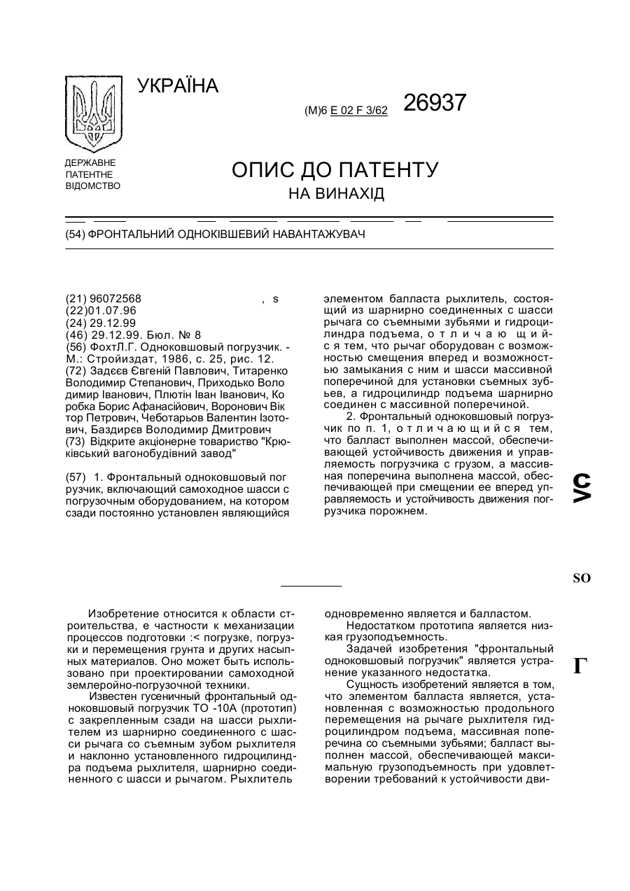
Номер патенту: 26937
Опубліковано: 29.12.1999
Автори: Воронович Віктор Петрович, Титаренко Володимир Степанович, Задєєв Євгеній Павлович, Плютін Іван Іванович, Баздирєв Володимир Дмитрович, Чеботарьов Валентин Ізотович, Коробка Борис Афанасійович, Приходько Володимир Іванович
МПК: E02F 3/32
Мітки: фронтальний, навантажувач, одноківшевий
Текст:
...устойчивости и управляемости движения погрузчика с грузом и порожнем. В целом заявляемый "фронтальный одноковшовый погрузчик" обладает существенными новыми свойствами. В сравнении с известными аналогами и прототипом он обладает расширенными технологическими возможностями, более высокой производительностью, надежностью, грузоподъемностью. На фиг. 1 показан фронтальный одноковшовый погрузчик, снаряженный для рыхления, вид сбоку; на...
Фронтальний агрегат
Номер патенту: 812
Опубліковано: 15.12.1993
Автор: Картавих Геннадій Йосипович
МПК: E21C 27/16
Мітки: фронтальний, агрегат
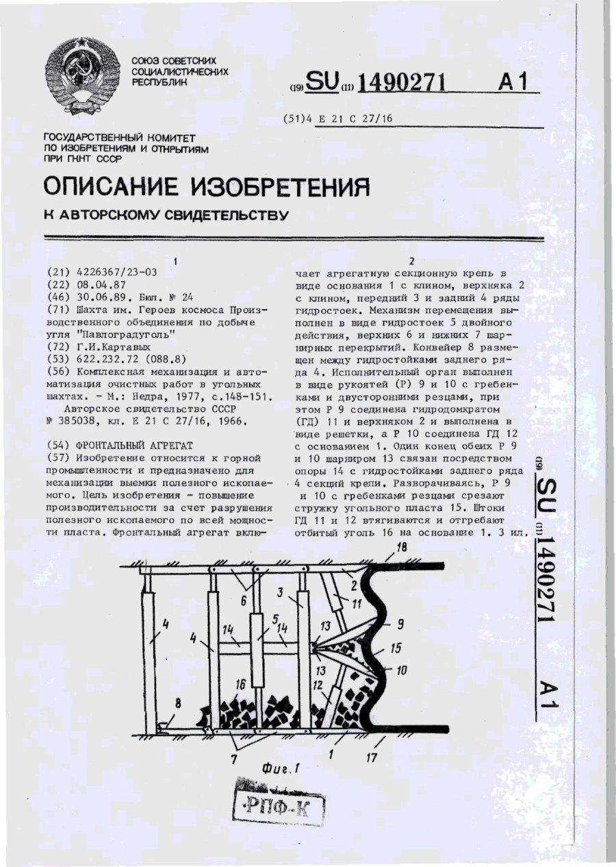
Формула / Реферат:
Ф о р м у л а и з о б р е т е н и яФронтальный агрегат, включающий агрегатную секционную крепь, выполненную в виде основания и верхняка с клиньями, переднего и заднего рядов гидростоек, механизм перемещения, конвейер, размещенный между гидростойками заднего ряда, и исполнительный орган, связанный посредством гидродомкрата с верхняком, о т л и ч а ю щ и й с я тем, что, с целью повышения производительности за счет разрушения полезного...
Фронтальний агрегат
Номер патенту: 8955
Опубліковано: 30.09.1996
Автори: Вінніков Іван Родионович, Літвінов Георгій Олексійович, Арутюнян Сурен Михайлович, Олексійчук Сидір Йосипович, Костюков Володимир Михайлович
МПК: E21C 27/32
Мітки: фронтальний, агрегат
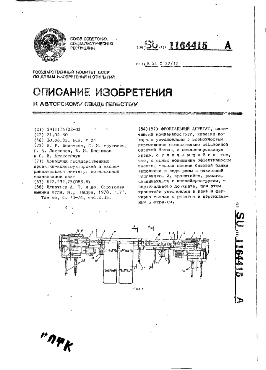
Формула / Реферат:
Фронтальный агрегат, включающий конвейероструг, каретки которого установлены с возможностью перемещения относительно секционной базовой балки, и механизированную крепь, отличающийся тем, что, с целью повышения эффективности выемки, каждая секция базовой балки выполнена в виде рамы с наклонной направляющей, кронштейна, рычага, соединенного с конвейеростругом, и вертикального домкрата, при этом кронштейн установлен в раме и шарнирно связан...
Фронтальний дощувач
Номер патенту: 863
Опубліковано: 15.12.1993
Автори: Дяченко Анатолій Костянтинович, Хорошавін Володимир Миколайович, Волобой Володимир Іванович, Севрюгін Віталій Костянтинович, Зеленський Генадій Мойсейович, Козлов Володимир Олександрович, Гацький Віктор Георгійович, Пацера Іван Павлович
МПК: A01G 25/09
Мітки: дощувач, фронтальний
Формула / Реферат:
1. Фронтальный дождеватель, включающий дождевальный аппарат с разнонаправленными стволами, имеющими разбрызгиватели струй с механизмами их регулирования, отличающийся тем, что разбрызгиватель струй выполнен в виде качающегося коромысла, на одном конце которого закреплен груз с изменяющимся центром массы, а на другом - рассекатель, выполненный в виде осесимметричных, разнонаправленных к оси ствола лопаток.2. Дождеватель по п. 1,...
Навантажувач кормів
Номер патенту: 30449
Опубліковано: 15.11.2000
Автори: Болтянський Борис Володимирович, Кисельов Олексій Васильович
МПК: A01D 87/00
Мітки: кормів, навантажувач
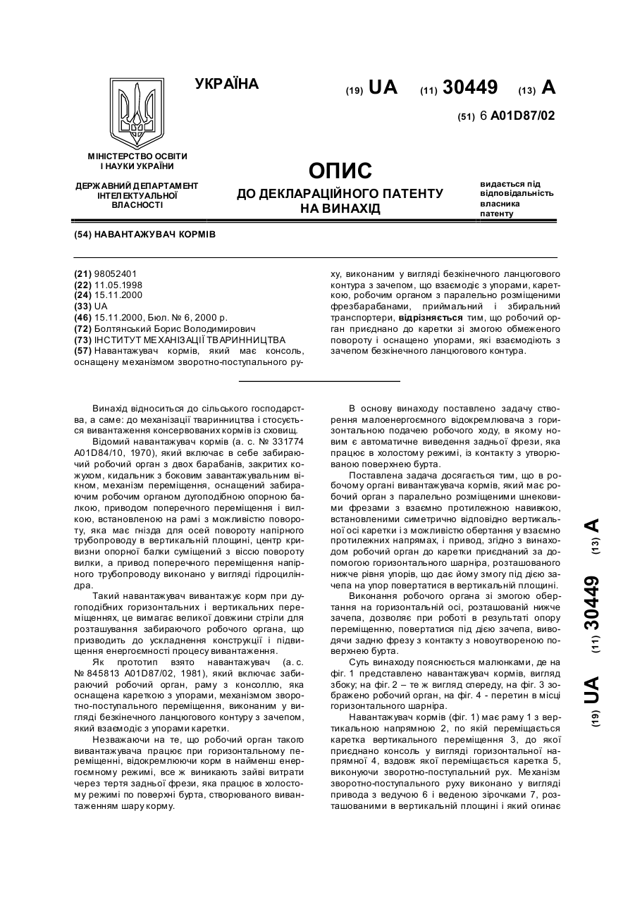
Формула / Реферат:
Навантажувач кормів, який має консоль, оснащену механізмом зворотно-поступального руху, виконаним у вигляді безкінечного ланцюгового контура з зачепом, що взаємодіє з упорами, кареткою, робочим органом з паралельно розміщеними фрезбарабанами, приймальний і збиральний транспортери, відрізняється тим, що робочий орган приєднано до каретки зі змогою обмеженого повороту і оснащено упорами, які взаємодіють з зачепом безкінечного ланцюгового...
Попередній патент: Пневматичний розподільник і сівалка з таким розподільником
Наступний патент: Спосіб синтезу сечовини та пристрій для його здійснення
Випадковий патент: Спосіб роботи двигуна внутрішнього згоряння