Пристрій для прокладання трубопроводів під водою
Номер патенту: 25865
Опубліковано: 26.02.1999
Автори: Браун Роберт У., ЛЕГЛЕУКС Майкл Джозеф, Уілкінс Джессі Рей

Формула / Реферат
1. Устройство для прокладки трубопроводов под водой, содержащее опорную конструкцию и направляющую систему для трубопровода, отличающееся тем, что направляющая система для трубопровода выполнена в виде подвижной платформы, шарнирно прикрепленной к опорной конструкции, и башни, прикрепленной к подвижной платформе и поддерживаемой опорной конструкцией и подвижной платформой в рабочем положении, кроме того, устройство снабжено подъемной траверсой для удержания трубной секции, установленной с возможностью доставки трубной секции в башню, талевым подвижным блоком для приема и удержания трубопровода, установленным с возможностью перемещения вдоль башни по всей ее длине, и опорным цоколем для приема трубопровода от талевого подвижного блока, установленным на подвижной платформе и выполненным с возможностью его перевода из первого, открытого для пропускания трубопровода положения, во второе, закрытое для пропускания трубопровода положение, и обратно.
2. Устройство по п.1, отличающееся тем, что снабжено внутренним центрирующим фиксатором, поддерживаемым башней и установленным с возможностью перемещения вдоль башни по всей ее длине, и средством для соосной установки внутреннего центрирующего фиксатора с трубной секцией при наращивании ее на трубопровод.
3. Устройство по п.2, отличающееся тем, что средство для соосной установки внутреннего центрирующего фиксатора снабжено корпусным элементом, установлено в башне с возможностью перемещения между первым, отведенным положением и вторым, выдвинутым положением.
4. Устройство по п.1 или 2, отличающееся тем, что подъемная траверса снабжена средством для центрирования трубной секции с трубопроводом.
5. Устройство по п.4, отличающееся тем, что средство для центрирования снабжено захватом для удержания трубной секции, выполненным с возможностью перемещения для центрирования трубной секции.
6. Устройство по пп.1, 2 или 4, отличающееся тем, что талевый подвижной блок выполнен с возможностью его перевода из первого, открытого для пропускания трубопровода положения, во второе, закрытое для пропускания трубопровода положение, и обратно.
7. Устройство по пп.1, 2 или 4, отличающееся тем, что оно снабжено стингером, прикрепленным снизу к подвижной платформе.
8. Устройство по пп.1 - 6 или 7, отличающееся тем, что оно снабжено устройством для размещения и складирования трубных секций.
9. Устройство по п.8, отличающееся тем, что устройство для размещения и складирования трубных секций содержит U-образный прямоугольный корпус с вертикально установленными разделителями, расположенными по ширине корпуса, и съемную горизонтальную опору, установленную в корпусе выше упомянутых разделителей и снабженную по ее ширине вертикально установленными разделителями.
Текст
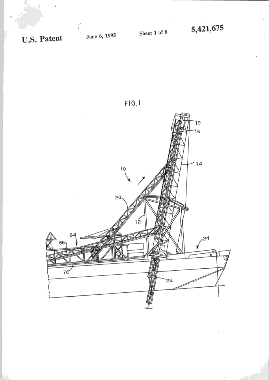
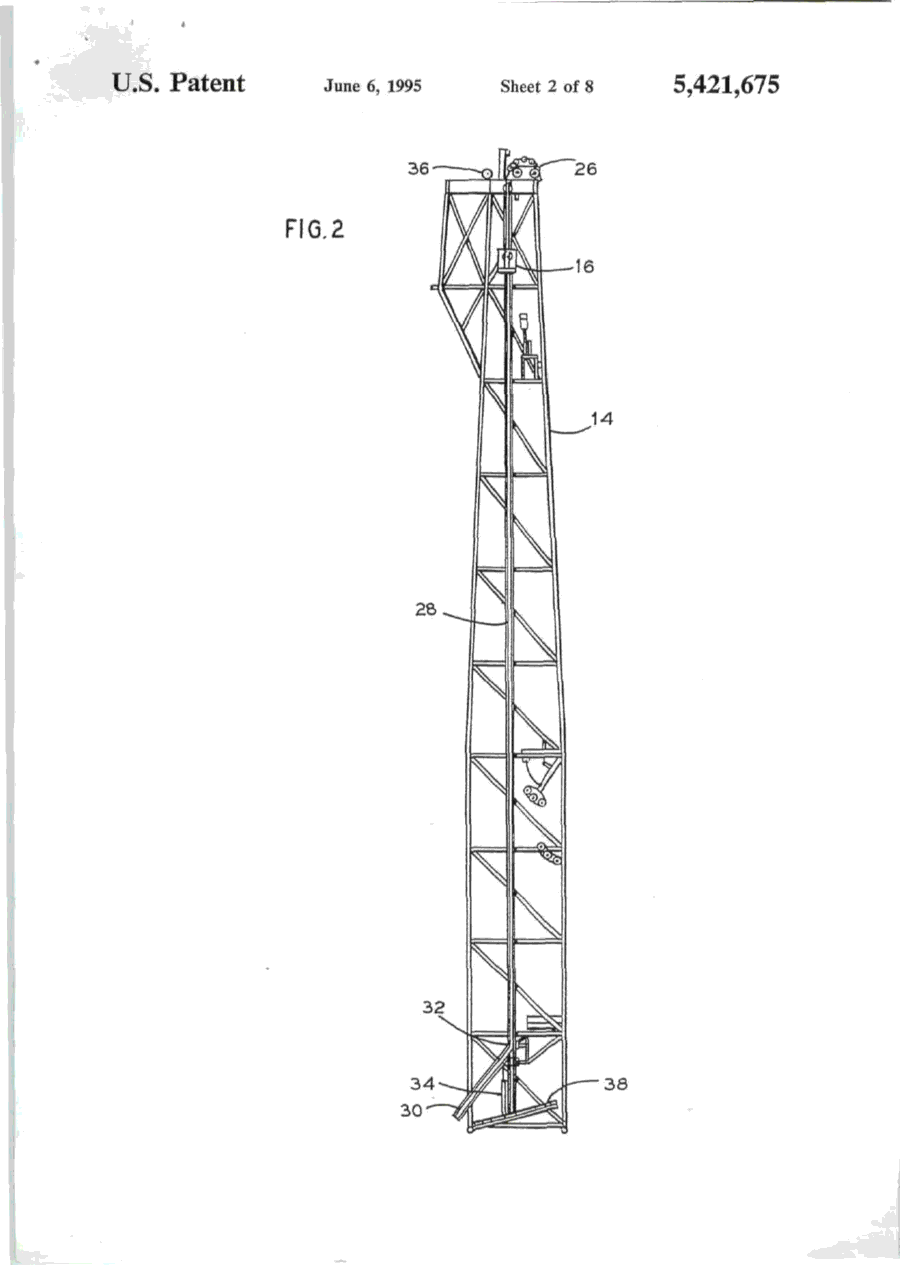
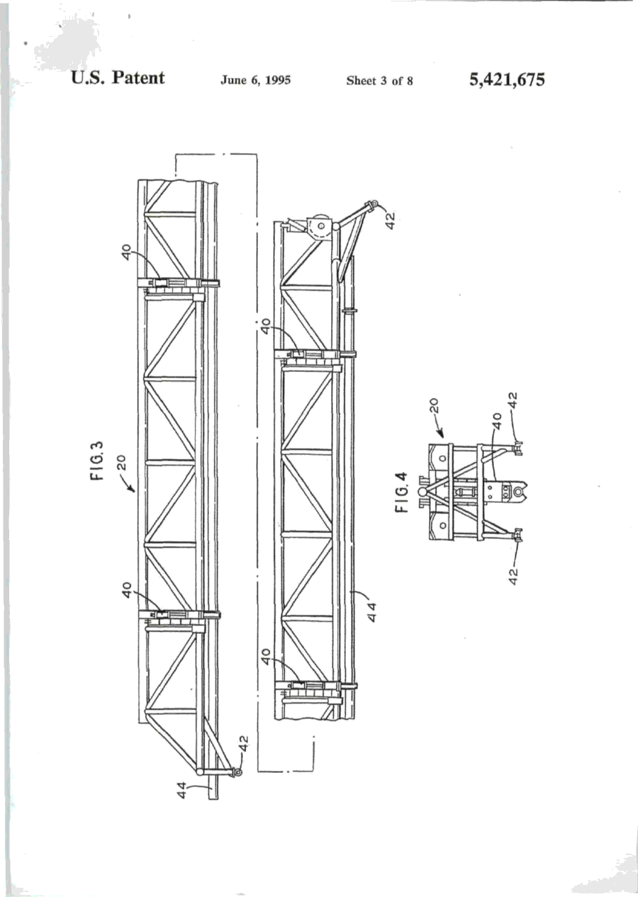
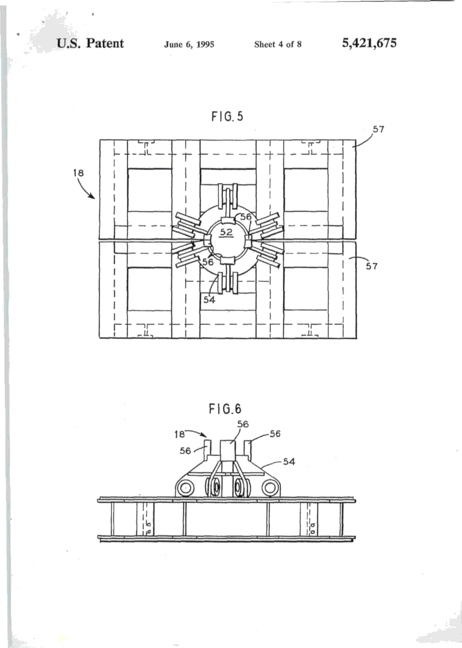
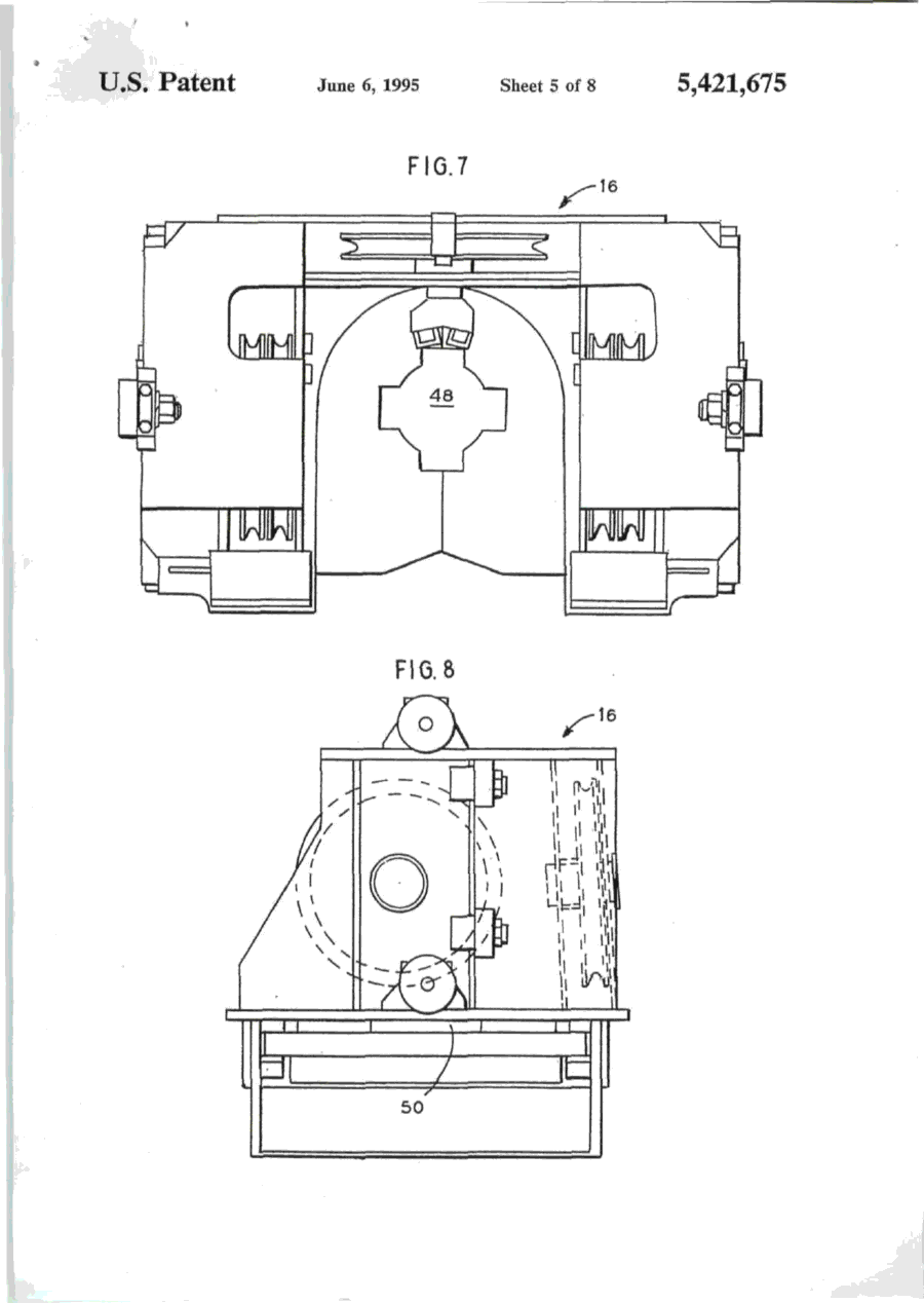
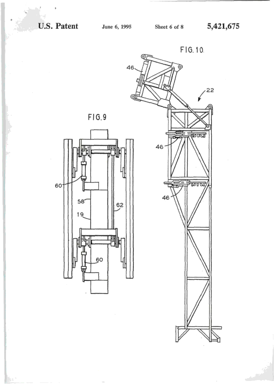
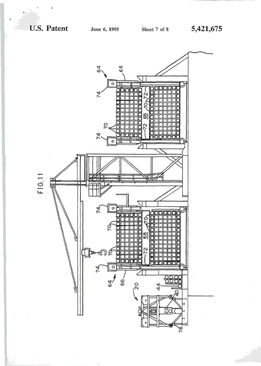
""41 L)bO0542I675A United States Patent [її] Patent Number: 5,421,675 Brown et al. [45] Date of Patent: Jun. 6, 1995 [54] APPARATUS FOR NEAR VERTICAL LAYING OF PIPELINE [75] Inventors: Robert W. Brown; Michael J . Legleux, both of New Orleans, La.; Jesse R. Wilkins, Picayune, Miss. [73] Assignee: McDermott International, Inc., New Orleans, La. [21] Appl. No.: 154,320 [22] Filed: [51] Int. Cl. [52] U.S. Q Nov. 18,1993 6 [58] Field of Search [56] B63B 35/04; F16L 1/00 405/170; 405/158; 405/166 405/154, 158, 166, 167, 405/169, 170, 165 References Cited U.S. PATENT DOCUMENTS 1,220,189 3,581,506 3,585,806 3,680,322 3.860.122 4,068,490 4.486.123 3/1917 6/1971 6/197] 8/1972 1/1975 1/1978 12/1984 Chapman Howard Lawrence Nolan et al Cemosek Jegousse Koch et al 405/167 405/166 405/166 405/166 405/166 X 405/166 405/169 FOREIGN PATENT DOCUMENTS 1532570 7/196S France 405/166 2204106 11/1988 United Kingdom 405/166 Primary Examiner—Dennis L. Taylor Assistant Examiner—John A. Ricci Attorney, Agent, or Firm—Robert J. Edwards; D. Neil LaHaye ABSTRACT [57] An apparatus for near vertical laying of pipeline offshore. A support frame and movable deck on a lay vessel support a tower at the desired angle for pipe laying. The tower has a travel block that is movable between open and closed positions for receiving a pipe section and supporting the weight of the pipe or pipeline. The travel block is adapted for movement along the length of the tower for raising or lowering the pipe and pipeline. A pedestal that is movable between open and closed positions for receiving a pipe section and supporting the weight of the pipeline is positioned near the bottom of the tower and adapted to transfer the weight of the pipeline from the travel block to the pedestal without the need to open the travel block. A strongback with adjustable clamps is used to grasp a pipe section from a ready rack and transfer the pipe section into the tower for addition of the pipe section to the pipeline. The strongback is guided into and up the tower by rails. A stinger extends down from the lower end of the tower and is provided with clamps to grip the pipeline during operations. The main portion of the stinger may be pivoted up adjacent the lay vessel when pipe laying operations are not in progress. 13 Claims, 8 Drawing Sheets \ 7 n U.S. Patent Sheet 1 of 8 6 5,421,675 '1995 FIG.l 19 16 U.S. Patent June 6, 1995 Sheet 2 of 8 FIG.2 32 5,421,675 U.S. Patent June 6, 1995 Sheet 3 of 8 5,421,675 I ' U.S. I Patent June 6, 1995 Sheet 4 of 8 FIG.5 FIG.6 56 5,421,675 > * U.S. Patent June 6, 1995 Sheet 5 of 8 5,421,675 FIG.7 FIG. 8 і \ \rtrI b\ \! 50 l U.S. Patent June 6, 1995 Sheet 6 of 8 5,421,675 FIG. 10 22 U.S. Patent і о June 6, 1995 Sheet 7 of 8 5,421,675 * * U.S. Patent June 6, 1995 FIG.12 Sheet 8 of 8 5,421,675 5,421,675 APPARATUS FOR NEAR VERTICAL LAYING OF PIPELINE amount of tension to the system. This system has never been used for deep water pipeline construction. Offshore pipe laying systems, those in use(S-lay) and theoretical proposals(J-Iay), have certain things in com5 mon. The systems may or may not use pipe add ons that have been multi-jointed outside the system to provide pipe joint lengths greater than the normal forty foot pipe length. Theoretical J-lay systems have proposed joint lengths of eighty feet or more. A single station is 10 used to accomplish the welding, NDT(non-destructive testing), and pipe coating of joints. In J-lay, it is necessary to have a means to transfer the pipe from the horizontal position on the lay vessel to a near vertical position on the by line. It is also necessary to have some 15 means of lowering the pipe as the lay vessel moves forward. A particular problem in this area has been the issue of devising an efficient manner of transferring the load of the pipeline to a holding mechanism so that the lowering mechanism can then be raised in preparation 20 for receiving the weight of the next pipe joint. What is lacking in the art is a system that provides an efficient, time saving means of transferring the pipe from the horizontal position to a near vertical position with the lay line, positioning the new pipe in alignment for weld25 ing to the existing pipeline, lowering the pipeline with the new pipe added, and then continuously repeating the process. BACKGROUND OF THE INVENTION 1. Field of the Invention The invention is generally related to the laying of pipeline offshore and particularly to the near vertical laying of pipeline offshore in deep water. 2. General Background The laying of offshore pipelines has been done for many years utilizing the technique referred to as S-lay. In the S-lay technique, joints of pipe are added to the pipeline in a horizontal position on the deck of a lay barge. The pipeline then curves over the stern of the barge, angles down toward the seabed, curves back to horizontal and lays on the seabed. The profile of the pipeline from the lay barge to the seabed is in the form of a long "S" which leads to the name of S-lay. Although S-lay has been the method of choice for virtually all pipeline installed to date, there are physical limitations on the use of this technique. Chief among these is water depth. As the water depth increases, the ability to move the vessel on anchors becomes more and more difficult and the horizontal component of the pipe tension becomes greater and greater. The offshore pipeline industry has been aware of this problem for years and has as a solution, accepted the concept of near vertical lay, called J-lay, as the system of choice for 30 deep water pipe laying. It should be understood that the definition of deep water, when referring to the use of J-lay, is a direct function of pipe diameter. This relationship is a result of the minimum water depth required for pipe of a certain diameter to achieve the proper flex 35 during the vertical laying operation. There is also a maximum practical depth for specific pipe diameters. As an example, pipe having a diameter of 6.625 inches requires a minimum water depth, with no water in the pipe, of 124 feet. At the opposite end of the scale, pipe 40 having a diameter of 42 inches requires a minimum water depth, with no water in the pipe, of 1,337 feet. Considerable work has been done over the years on the theoretical aspects of the J-lay concept, but very 45 little work has been done on the actual hardware and equipment needed for this type of system. Most of the systems proposed have utilized existing semi-submersible drilling units. These units, which are capable of being modified for this service, were not built to be used 50 as pipe layers and can not be made to be very efficient during pipe laying operations. Another problem area in laying pipeline offshore is the storage, transportation, and transfer of pipe to the lay vessel. In normal operations, the line pipe for the 55 pipeline is transported to the field in forty foot long joints. The transport vessel, which is usually a small material barge or a special purpose pipe haul boat, is tied to the side of the lay vessel as the pipe is transferred to the lay vessel. Transfer of the pipe one joint at a time 60 may take several days. The transfer of pipe from between vessels subject to sea induced motion is hazardous to personnel and equipment under good sea conditions and becomes impossible to do safely under bad conditions. 65 Applicants are aware of a system that utilizes a ramp that can be adjusted from horizontal to vertical. It uses large tensioners to grip the pipe and apply the necessary SUMMARY OF THE INVENTION The present invention addresses the above needs in a straightforward manner. What is provided is an apparatus for near vertical laying of a pipeline offshore. Pipe bins are provided that are capable of storing, transporting, and transferring between vessels up to twenty-five thousand feet of twelve and three-quarter inch outer diameter pipe. A pipe ready rack is positioned on the lay vessel adjacent a pipe bin for receiving a single prepared pipe joint. A strongback is used to lift the pipe joint from the ready rack and move it into a near vertical position in a tower on the lay vessel. The pipe joint is aligned and held in position over the pipeline by the strongback clamps (support type) and a weld clamp while the pipe joint is welded to the pipeline. A travel block supported by the tower receives the weight of the pipe joint and pipeline via a buckle arrester on the pipe and is used to lower the pipeline while the lay vessel moves forward in preparation to add another pipe joint. A pedestal on a movable deck receives the weight of the pipeline on the buckle arrester from the travel block and supports the pipeline while another pipe joint is being positioned for welding to the pipeline. The strongback is capable of being lowered to pick up and raise a pipe joint during thefinalwelding phases to have a new pipe joint in position for welding to the pipeline as soon as possible after the pipeline is lowered. BRIEF DESCRIPTION OF THE DRAWINGS For a further understanding of the nature and objects of the present invention reference should be had to the following description, taken in conjunction with the accompanying drawings in which like parts are given like reference numerals and, wherein: FIG. 1 is an elevation view of the invention. FIG. 2 is an elevation view of the tower. FIG. 3 is an elevation view of the strongback. FIG. 4 is an end view of the strongback. FIG. 5 is a plan, view of the pedestal. FIG. 6 is an elevation view of the pedestal. 5,421,675 Strongback 20, seen in FIG. 3 and 4, is formed from a triangular shaped frame and is provided with a plurality of clamps 40 spaced along its length. Each end of strongback 20 is provided with rollers 42 that are sized to be received in rails 28 and 30 on tower 14. In its operational position, the flat portion of the triangle of strongback 20 faces the deck of the lay vessel on tower 14 and clamps 40 extend from the flat portion for gripping a pipe joint 44. Clamps 40 are adjustable so as to be capable of moving between a first retracted position and a second extended position to allow alignment of the pipe joint 44 with the pipeline for welding. DETAILED DESCRIPTION OF THE PREFERRED EMBODIMENT Stinger 22, seen in FIG- 1 and 10, is attached to the Referring to FIG. 1, it is seen that the invention is 1 5 bottom of the movable work deck 13 (FIG. 12) and generally indicated by the numeral 10 Apparatus 10 for designed to provide support to the pipeline as it is lowe r e d d u n n near vertical laying of pipeline is generally comprised of 8 forward movement of the lay vessel, support frame 12, movable deck 13, tower 14, travel Stinger 22 is formed from two sections that are pivotа11 block 16, pedestal 18 seen in FIG. 5 and 6, internal pipe У attached to each other. The lower section is mova b l e b e l w clamp 19 seen in FIG. 9, strongback 20, and stinger 22. e e n a first retracted or folded position and a Support frame 12 is of any suitable shape and rigidly 2 0 вес°п? «tended position relative to the upper section a n d t h e w o r k deck attached to the lay vessel 24. In the preferred embodi- I n t h e £ * P 0 5 " 1 0 "- t h e b ^ e r section is positioned substantially parallel to the hull or the ment, support frame 12 is adapted to pivotally receive lay vessel to present little or no resistance to movement movable deck 13 and tower 14 such that they may be of the vessel when pipe laying operations are not undermoved between a first operative pipe laying position „, _,. . , , ,. , , , . . . , , .•«. , • т-т/^ , 25 way. This also prevents damage to the stinger. In the that includes several different angles as seen in FIG. 1 i. , , jf5-. • -_, J • L *і_ , , , ... - °c , , . preferred embodiment, stinger 22 is provided with three and a second stowed position for safety purposes during , . , ., ^ . ,°, _ ,L - v j ґ J To achieve this, г к ^ clamps 46 that can be used to support the pipeline durrough seas or travel of the lay vessel. ing welding of a new pipe joint onto the pipeline. movable deck 13 is pivotally attached at one side of its lower end to support frame 12 and can be rigidly at- 3 Q Stinger 22 matches the angle of tower 14 during pipe ^"і^о7егі\]опГ tached at the opposing side of the lower end to support Travel block 16 seen in FIG and 8, is adapted to frame 12 as seen in FIG. 12. A variety of attachment support the weight of a pipe joint or the pipeline. As points are provided so that deck 13 and tower 14 can be seen in FIG. 7, travel block 16 is formed from two set at the desired angle. A winch and cables are used to sections each having a cutout that defines an opening 48 raise and lower tower 14. 35 with a diameter sized to receive a section of pipe when As seen in the detail view of FIG. 12, tower 14 is the two travel block sections are adjacent each other. mounted on movable deck 13. Work deck 15 may be The two sections of travel block 16 are movable bepivotally attached to tower 14 or deck 13 so as to be tween a first closed position adjacent each other and a adjustable to a horizontal position for personnel. Tower second open position. The diameter of opening 48 is 14, seen in FIG. 2, is a U-shaped frame open on one side smaller than the diameter of buckle arresters 50, seen in elevation in FIG. 8, that are attached to the pipe at along its length and is designed to support the weight of predetermined intervals. Opening 48 is shaped to define the pipeline during the lowering or raising of the pipefour rectangular extensions equally spaced apart in an line and to receive and guide the strongback into posiotherwise circular opening. The significance of the tion in the tower so that a pipe joint may be added to the pipeline. Travel block 16 is received in tower 14 and 4 5 s h a p e of opening 48 will biT explained below. It can be supported by a cable sheave assembly 26 mounted on faal w n e n j n the first closed position, travel block s e e n top of tower 14. Pedestal 18, seen in FIG. 5 and 6, is іб will not allow passage of buckle arrester 50 attached mounted on an adjustable work deck 38 at the lower o a pipe 44 and travel block 16 can be used to support t end of tower 14. Internal pipe clamp 19 is movably i joint during welding of a pipe joint onto the a p pe positioned adjacent the top of tower 14. Means for 50 pipeline or during lowering of the pipeline by lowering guiding strongback 20 into and out of tower 14 is proof travel block 16 in tower 14. In the second open posivided m the form of a pair of raits 28 on opposing sides t i o n , opening 48 is large enough to allow passage of of the tower that receive rollers on the strongback. A buckle arrester 50. pair of transition rails 30 extend from the lower end of Pedestal 18, seen in FIG. 5 and 6, is similar to travel tower 14 at an angle to aid in the transition period when 55 block 16 in that it is formed from two sections that are the strongback is moving between a position horizontal designed to be movable between a first closed position to the deck of the lay vessel and into or out of tower 14. and a second open position. When in the first closed A rail switch 32 is used at. the junction of rail 28 and position, the two sections define a circular opening 52 transition rail 30 to allow downward movement of sized to receive the pipe being used to lay the pipeline, strongback 20 in tower 14 once a pipe joint has been 60 Base 54 is provided with four vertically extending brought into tower 14 by strongback 20. A pair of hyblocks 56 spaced equally around the circumference of drauhc cylinders 34 attached to the lower end of tower opening 52 that are sized to be of lesser diameter than 14 are positioned to receive and support strongback 20 buckle arrester 50 when pedestal 18 is in its first closed during certain phases of the operation. Sheave 36 on the position. Blocks 56 are positioned so as to be m aligntop of tower 14 provides a support point for a cable that 65 ment with the four rectangular extensions in opening 48 is attached to one end of strongback 20 and is used in in travel block 16. This allows for a direct transfer of the conjunction with a winch to raise and lower strongback weight of a pipe joint or the pipeline via buckle arrester 20 into and out of tower 14. 50 from travel block 16 to pedestal 18 as travel block US FIG. 7 is a plan view of the travel block. FIG. 8 is an elevation view of the travel block. FIG. 9 is an elevation partial phantom view of the internal line up clamp and handling system. FIG. 10 is an elevation view of the stinger. FIG. 11 is an elevation facing sternward on the lay vessel that illustrates the pipe bins, pipe ready rack, and strongback. FIG. 12 is a detail view that illustrates the movable 10 deck. 5,421,675 is used to lower the pipeline. Blocks 56 protrude through the rectangular extensions in opening 48 as travel block 16 is lowered and engage buckle arrester 50 to provide an automatic weight transfer to pedestal 18. Travel block 16 is then moved to its second open posi- 5 tion to clear the buckle arrester and may then be moved back up to the top of tower 14 in preparation for the next pipe joint to be added to the pipeline. Base 54 is supported by two separate plates 57 that are movable relative to each other. As seen in FIG. 12, pedestal 18 is 10 supported by movable deck 13 and aligned with a hole provided therethrough. Internal pipe clamp 19, seen in phantom view in FIG9, is retained inside a housing 58 that serves as a means for aligning and inserting clamp 19 with and into a pipe 15 joint 44 that is being held in tower 14 by strongback 20. Alignment means is necessary for the following reasons. The pipe laying operations are conducted in a near vertical position. As a result, it would be extremely difficult or impossible to lower clamp 19, hanging by a 20 cable in a normal vertical position, into a pipe that is not in a vertical position due to the position of tower 14 and strongback 20. Housing 58 is sized to be received over the end of the pipe so that clamp 19 is easily lowered into the pipe for welding operations. Means for posi- 25 tioning housing 58 over the pipe is provided in the form of hydraulic cylinders 60 that are attached to tower 14 and adapted via arms 62 to cause the desired movement of housing 58 between a first retracted position and a second extended position in alignment with the pipe 30 joint. guided into tower 14 on rails 30 and 32. The tower may be set from zero degrees to a fifteen degree angle from vertical in the preferred embodiment for laying of pipe in deep water. Clamps 40 on the strongback are used to move the pipe joint into alignment with the pipeline. Rail switch 32 is moved to allow the strongback to move down in tower 14 and onto strongback lowering cylinders 34. The strongback is lowered by cylinders 34 until the end of the pipe joint is the proper distance from the end of the pipeline. Housing 58 is moved into alignment with the top of the pipe joint, internal pipe clamp 19 is lowered into the pipe joint to the proper position at the junction of the pipe joint and pipeline, and pipe clamp 19 is actuated to clamp the ends of the pipe joint and pipeline in the proper position for welding. Travel block 16 is positioned below the upper end of the pipe joint and closed around the buckle arrester on the pipe joint. In the preferred embodiment, strongback 20 and clamps 40 are used to support the pipe joint during the first three weld passes. Clamps 40 are then released from the pipe joint and retracted to allow strongback. 20 to be moved out of tower 14 to pick up another pipe joint from ready rack 76. During this time, travel block 16, pedestal 18, and clamps 46 on stinger 22 are used to support the weight of the pipe joint and pipeline during the final welding, examination, and coating process. After the process is completed, clamps 46 on the stinger are opened and travel block 16 is lowered in tower 14 while the lay vessel 24 moves forward. Vertically extending blocks 56 on pedestal 18 protrude through the rectangular cut outs in travel block 16 and receive the weight of the pipeline. Travel block 16 is then opened FIG. 11 is an end view of pipe bins 64 that provide for and raised m tower 14 and strongback 20 is used to the storage, transport, and transfer between vessels of position the next pipe joint in alignment for welding to pipe joints to be used in a pipe laying operation. Prior the pipeline and the process is repeated. The ability to art containers were unable to store a large quantity of 35 transfer the load to the pedestal, free the travel block to pipe without crushing the pipe at the bottom of the move back into position, and have the next pipe joint container and did not provide a safe way of transferring ready for alignment and welding to the pipeline helps to large quantities of pipe from one vessel to another. Pipe minimize time required to add pipe joints to the pipebins 64 solve these problems. A rectangular U-shaped line. frame 66 seen in FIG. 1 is divided into upper and lower 40 storage sections and is provided with a plurality of Because many varying and differing embodiments vertically extending horizontal spacers 70. Horizontal may be made within the scope of the inventive concept supports 68 are removably received in and supported by herein taught and because many modifications may be rectangular frame 66. Each support 68 is also provided made in the embodiment herein detailed in accordance with a plurality of vertically extending horizontal spac- 45 with the descriptive requirement of the law, it is to be ers 70 that are spaced apart according to the size pipe to understood that the details herein are to be interpreted be used in the pipe laying operation. As seen m the end as illustrative and not in a limiting sense. view of FIG. 11, horizontal supports 68 are provided What is claimed as invention is: with a flange 72 on each end that is received in frame 66 1 An apparatus for near vertical laying of a pipeline to place the load of support. 68 and the pipe loaded 50 offshore, comprising: thereon on rectangular frame 66 instead of the pipe in a. a support frame; the lower section of frame 66. Horizontal spacers 70 are b. a movable deck pivotally attached to said support provided at suitable intervals along the length of supframe; ports 68 and the bottom of frame 66. Horizontal spacers с a tower attached to said movable deck and sup70 prevent the pipe from rolling in the bin during rough 55 ported by said frame and said movable deck in a seas and presenting a safety hazard or damaging the near vertical position; pipe. Any suitable supporting material such as lumber d. a strongback adapted to hold and deliver a pipe may be used between layers of pipe to evenly spread the section into said tower; load and prevent direct pipe contact that could damage the ends of the pipe. Padeyes or lifting bales 74 are 60 e. a travel block adapted for movement along the length of said tower and for receiving and supportprovided on frame 66 to allow transfer of pipe bin 64 ing the weight of the pipeline; and all pipe stored therein in a single operation f a pedestal supported by said movable deck and In operation, a single pipe joint 44 has the ends preadapted to receive and support the weight of the pared for welding to the pipeline and is transferred to a pipeline from said travel block, said pedestal being pipe ready rack 76. As seen in the end view of FIG. 11, 65 movable between a first open and a second closed strongback 20 is lowered over ready rack 76 and clamps position; and 40 are used to grasp pipe joint 44. As seen in the seg. a clamp adapted to hold and align a pipe section quence of FIG. 1, strongback 20 is then pulled up and held by said strongback in said tower with the 5,421,675 pipeline for addition thereto, said clamp being movable between a first retracted position and a second extended position. 2. The apparatus of claim 1„ wherein said travel block is movable between a first open and a second closed position. 3. The apparatus of claim 1, further comprising a stinger attached to the lower end of said movable deck. 4. An apparatus for near vertical laying of a pipeline offshore, comprising: a. a support frame; b. a movable deck pivotally attached to said support frame; c. a tower attached to said movable deck and supported by said frame and said movable deck in a near vertical position; d. a strongback adapted to hold and deliver a pipe section into said tower; e. a travel block adapted for movement along the length of said tower and for receiving and supporting the weight of the pipeline; f. a pedestal supported by said movable deck and adapted to receive and support the weight of the pipeline from said travel block, said pedestal being movable between a first open and a second closed position; g. an internal pipe clamp supported by said tower and adapted for movement along the length of said tower; and h. means for aligning said internal pipe clamp with a pipe section held in said tower for addition to the pipeline. 5. The apparatus of claim 4, wherein said alignment means for said internal pipe clamp comprises a housing attached to said tower and movable between a first retracted position and a second extended position. 6. The apparatus of claim 4, wherein said travel block is movable between a first open and a second closed position. 7. The apparatus of claim 4, further comprising a stinger attached to the lower end of said movable deck. ю 15 20 35 40 45 50 55 60 8 8. The apparatus of claim 4, further comprising means for aligning a pipe section held by said strongback in said tower with the pipeline for addition thereto. 9. The apparatus of claim 8, wherein said alignment means comprises a clamp adapted to hold a pipe section and be movable between a first retracted position and a second extended position. 10. An apparatus for near vertical laying of a pipeline offshore, comprising: a. a support frame; b. a movable deck pivotally attached to said support frame; с a tower attached to said movable deck and supported by said frame and said movable deck in a near vertical position; d. a strongback adapted to hold and deliver a pipe section into said tower; e. means for aligning a pipe section held by said strongback in said tower with the pipeline for addition thereto; f. a travel block adapted for movement along the length of said tower and for receiving and supporting the weight of the pipeline; g. a pedestal supported by said movable deck and adapted to receive and support the weight of the pipeline from said travel block, said pedestal being movable between a first open and a second closed position; h. an internal pipe clamp supported by said tower and adapted for movement along the length of said tower; and І. means for aligning said internal pipe clamp with a pipe section held in said tower for addition to the pipeline. 11. The apparatus of claim 10, wherein said alignment means for a pipe section held by said strongback comprises a clamp adapted to hold a pipe section and be movable between a first retracted position and a second extended position. 12. The apparatus of claim 10, wherein said travel block is movable between a first open and a second closed position. 13. The apparatus of claim 10, further comprising a stinger attached to the lower end of said movable deck.
ДивитисяДодаткова інформація
МПК / Мітки
МПК: B63B 35/00, F16L 1/12
Мітки: водою, трубопроводів, пристрій, прокладання
Код посилання
<a href="https://ua.patents.su/13-25865-pristrijj-dlya-prokladannya-truboprovodiv-pid-vodoyu.html" target="_blank" rel="follow" title="База патентів України">Пристрій для прокладання трубопроводів під водою</a>
Установка для безтраншейного прокладання трубопроводів в грунті
Номер патенту: 24275
Опубліковано: 07.07.1998
Автор: Резніченко Віктор Петрович
Мітки: установка, трубопроводів, безтраншейного, прокладання, грунті
Формула / Реферат:
1. Установка для бестраншейной прокладки трубопроводов в грунте, включающая рабочий орган и размещенный на направляющих силовой агрегат с приводом вращения, приводом продольного перемещения и устройством для закрепления трубы-патрона, в которой рабочий орган выполнен в виде шнека с режущей головкой и кинематически связан с приводом вращения, привод продольного перемещения содержит силовой цилиндр и передвижной упор, жестко соединенные между...
Фланцеве з’єднання трубопроводів

Номер патенту: 11723
Опубліковано: 25.12.1996
Автори: Ткаченко Леонід Георгійович, Філіпп'єв Анатолій Михайлович, Шагін Олег Володимирович
МПК: F16L 23/00
Мітки: фланцеве, з'єднання, трубопроводів
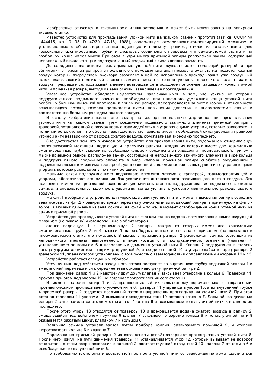
Пристрій для прокладання уточної нитки на ткацькому верстаті
Номер патенту: 12613
Опубліковано: 28.02.1997
Автор: Аксюков Віталій Леонідович
МПК: D03D 47/28, D03D 47/00
Мітки: прокладання, пристрій, уточної, ткацькому, нитки, верстаті
Формула / Реферат:
Устройство для прокладывания уточной нити на ткацком станке, содержащее отмеривающе-компенсирующий механизм, подающую и приемную рапиры, каждая из которых имеет две коаксиально смонтированные трубки, мыски на свободных концах и соединена с приводом и пневмосистемой, причем, в мыске приемной рапиры расположен зажим, состоящий из неподвижного зажимного элемента в виде кольца и подпружиненного подвижного элемента в виде клапана, отличающееся...
Пристрій кріплення трубопроводів
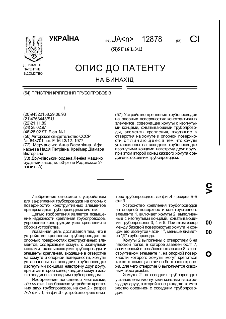
Номер патенту: 12878
Опубліковано: 28.02.1997
Автори: Креймер Діамара Вікторівна, Мерчанська Анна Василівна, Афанасьєва Надія Петрівна
МПК: F16L 3/12
Мітки: кріплення, пристрій, трубопроводів
Формула / Реферат:
(57) Устройство крепления трубопроводов на опорных поверхностях конструктивных элементов, содержащее хомуты с изогнутыми концами, охватывающими трубопроводы, элементы крепления, входящие в отверстия на хомуте и опорной поверхности, отличающееся тем, что хомуты установлены на соседних трубопроводах изогнутыми концами навстречу друг другу, при этом второй конец каждого хомута соединен с соседним трубопроводом.
Пристрій для ведення вибухових робіт під водою
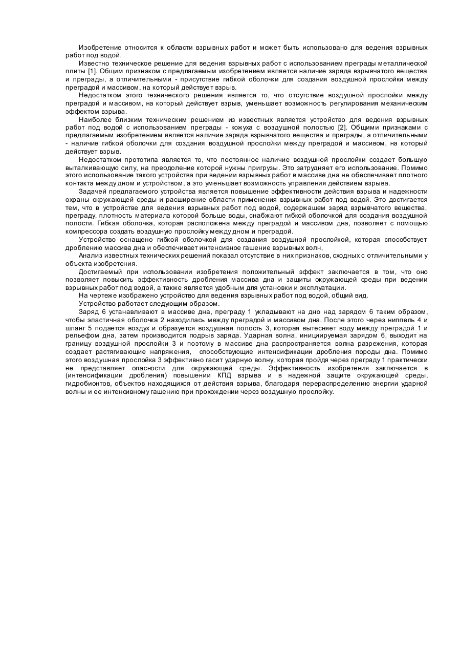
Номер патенту: 23773
Опубліковано: 16.06.1998
Автори: Луговий Микола Петрович, Ткачук Костянтин Ніфонтович, Луговий Петро Захарович, Луговий Захар Петрович, Гуляєв Валерій Іванович, Митюк Людмила Олексієвна
МПК: F42D 5/00
Мітки: пристрій, ведення, вибухових, робіт, водою
Формула / Реферат:
Устройство для ведения взрывных работ под водой, содержащее заряд взрывчатого вещества, преграду, отличающееся тем, что преграда снабжена гибкой оболочкой, расположенной между преградой и объектом, в котором заложен заряд.
Попередній патент: Широкосмуговий оптичний підсилювач
Наступний патент: Пристрій для різки труб
Випадковий патент: Спосіб одержання подвійного дифосфату літію-феруму (ііі)