Спосіб бездротового підключення абонентів до комутованої мережі зв’язку
Номер патенту: 32966
Опубліковано: 15.02.2001
Автори: Владишевський Борис Сергійович, Воробієнко Петро Петрович, Нечипорук Олег Леонідович

Текст
mill US005311570A United States Patent [i9] [11] Patent Number: 5,311,570 Grimes et al. [45] Date of Patent: May 10, 1994 62-179254 1/1988 Japan . 0296846 11/1989 Japan 2158678 11/1985 United K.ingdom 2222503 3/1990 United Kingdom H04M 1/64 ... 379/57 H04Q 7/00 H04Q 7/04 [54] INTEGRATION OF WIRELESS PAGING IN A COMMUNICATION SYSTEM [75] Inventors- Gary J. Grimes, Thornton; Lawrence J. Haas, Broomfield, both of Colo. [73] Assignee: [21] Appi. No.: 699,084 [57] [22] Filed: [51] [52] Int. a . ! . . U.S. a [58] Field of Search A communications switching system such as a PBX, central office switch and the like, responds to an incom ing call to d called parly by signaling a paging device as well as some other communications device having com munications capability difTerent from that of the paging device In the disclosed embodiment, which pertains to a private branch exchange (PBX), this other communi cations device )s one which provides two-way voice communications Advantageously, the paging device may also be provided with the capability of signalling the communications system that the called party will shortly answer the call via a communications device possessing two-way voice communications Upon re ceipt of this pager-Iransmitted signal, the communica tions system, if desired, can be provided with the ability to provide an announcement to the calling party of the called party's intent to answer the call. Once the called party reaches any voice communications device con nected to the system, the incoming call is redirected to that device upon the called party providing a predeter mined identification to the communications system [5^ Primary Examiner—Curtis Kuntz Assistant Examiner~Q. J Oehling Attorney, Agent, or Firm—David R. Padnes АТЛТ Bell Laboratories, Murray Hill, N.J. May 10, 1991 H04M 11/00 379/57; 379/58, 340/825.44 379/56, 57, 58, 67, 379/59, 170, 340/825 44 References Cited U.S P A T E N T D O C U M E N T S 4,608,458 4,637,022 4,642,425 4,658.416 4,661.972 4,680,785 4,748,655 4,906,989 4,940,963 5,109,405 5,117,449 8/1986 1/1987 2/1987 4/1987 4/І987 7/1987 5/1988 3/1990 7/1990 4/1992 5/1992 Hashimoto Burke et ai Guinn, Jr et al Tanaka Kai Akiyama et al Thrower ct al Kasugai Gulman et al Morganstem . . Metroka et al 179/2 A 455/311 379/57 379/57 379/56 J79/57 379/57 X 379/56 379/57 379/67 379/58 FOREIGN PATENT DOCUMENTS 2541020 8/1984 France ABSTRACT 19 Claims, 8 Drawing Sheets G08B 5/00 і:б. твті 101-1 , C1BCUII 1 ClflCUfl Ш:. —і V' ІЩГШйШШііїІ 102 1 І;І Р шБІ 11! І . ^.^^і-^ошш^щ :х 101-И («й£І) COMKJNCIIICKSI і І}Е. таї „2-0 TRUKK lU-l ШНГдСС lis X Х1> ^ п Г ^ V I E M I SffTBS O C AL "*] lOi race «AIL sijiui W •4t»l B S 106 U л 107-^ СОКІКИ СШРІП j PKoassoJi ] т ^ H-JUS lOSСАЦ PHOCESSOli P O B WMMT R GU mwsiiiibK iJ[if«' p .11! СР Ш 1 ІС І I nifuf ЙЕшГ •112 5,311,570 INTEGRATION OF WIRELESS PAGING IN A COMMUNICATION SYSTEM TECHNICAL FIELD 5 The present invention relates to communications systems and, more particularly, to a technique for inte grating the call processing of incoming calls to a called party associated with both wireless paging and another wired or wireless communications device possessing "^ full two-way communications capabilities BACKGROUND OF THE INVENTION A vanety of wired and wireless communications devices, each oiTenng a panoply of capabilities, are available to suit an individual's needs Wired communi cations devices are those which require a signal-con ducting path, other than air between the communica tions device and a communications s>stem such as a central office switch or pnvate branch exchange (PBX) The signal-conducting path can take many physical forms including a number of different kinds of metallic conductors or optical fibers In contrast, wireless com munications devices, such as paging and cellular radio communications devices, utilize the air as the medium to transport signals to and from the communications system The distinction between pagmg and cellular radio devices resides in their communications capabih lies Paging devices are portable one-way communica tions devices which respond to associated radio signals which are broadcasted while cellular radio devices provide full two-way communications capabilities '^ 20 ^5 30 With a paging device, the reception of a predeter mined radio signal typically activates an audible and/or visual alarm to indicate that the person carrying the 35 pager should make л call to a predetermined telephone number to receive a message Or, in the alternative, the pagmg device may have the capability to receive an incoming message which can be displayed This mes sage communicates a predefined amount of information 40 which may be the telephone number of a calling party There are man> situations where an individual may have a pager as well as a wired or wireless communica tions device possessing full two way communications capabilities to receive incoming calls Such situations 45 mclude a hospital, manufaclunng, education and gen eral office environments where it is desirable that an individual be notified of incoming calls independent of whether that individual is ш close proximity to his/her associated full, two-way communications device In 50 such situations, it is necessary that a communications system have the capability of notifying a called party of an incoming call by signalling any paging device associ ated with that called party Present techniques which provide such signalhng broadcast a s ^nal to the paging 55 device associated with the called paily The shortcom ing of this technique is that a telephone number differ ent from that associated with the called party must be dialed m order to activate such a broadcast As a result, a calling party must dial two different telephone num- 60 bers, the first associated with the called party's wired full two-way or wireless communications device and then, if the called party does not answer, dials a second number to alert the called party via his/her paging device If the second number IS dialed, the caUing party 6^ must also wait for a return call from the called party since the paging device cannot provide two-way com munications capabilities This scenano often results in 2 considerable telephone tag, i e, situations where two individuals periodically try to contact one another and fail because the other person is unavailable While the use of cellular communications devices with full two-way communications devices can allevi ate much of the foregoing problems associated with paging devices, cellular radio devices give nse to a set of other problems One such problem is that cellular telephones are expensive and this expense is not merely that of the portable communications device but also that of the necessary transceivers which must be disposed to provide substantially uniform communications cover age within a given environment It should be noted m this regard that the requirements of supporting appara tus associated with two-way cellular radio devices are considerably more sophisticated than those associated with paging devices because the former must provide mlclligible two-way communications Another problem IS that the requirements for cellular two way radio de vices may be difficult, if not impossible, to achieve m certain noisy environments Still another problem is that the required radio spectrum to provide cellular radio communications maj not be available in certain envi ronments or geographical areas In light of the foregoing, there are still considerable applications for paging devices and it would be desir able if a scheme could be devised which would ehminate the problems associated with the use of such de vices SUMMARY OF THE INVENTION In accordance with a broad aspect of the present invention, a communications system, such as a PBX, central office switch and the like, responds to an incom ing call to a called party bv signaling apagmg device and some other communications device having commu nications capabilities different from that of the paging device In the disclosed embodiment this other commu nications device IS one having two-way voice communi cations capability Additional aspects can also be pro vided In the disclosed embodiment, for example, the paging device IS provided with the capability of signal ling the communications system that the called party will shortly answer the call via a communications de vice which provides two way voice communications Upon recejpl of this signal, (he communiLaiions system, if desired, may be also provided with the ability to provide an announcement to the calling party of the called party's intent to answer the call In any event, if the paging device is provided with the aforementioned ability to transmit a signal to the communications sys tem, when the called party reaches any two-way voice communications device connected to the communica tions system, the incoming call can be redirected to that two-way device BRIEF DESCRIPTION OF THE DRAWING FIG 1 IS a block-schematic diagram of an exemplary communications system incorporating the present in vention, FIGS 2 and 3 are representations of the translation and status data respectively stored in the translation and status memones of the system of FIG 1, FIG 4 IS a representation of the physical arrange ment of an exemplary wired or wireless communica tions device possessing full two way communications 5,311,570 transmission capabihty wherein a called party who is capabilities for use in the communications system of away from his associated wired or wireless communicaFIG 1 tions device can signal call processor 109 within control FIG 5 IS a representation of the physical arrangecomplex 105 of an intent to respond to the call Having ment of an exemplary pager for use m the communica5 such an intent, the called party can go to any of the tions system of FIG 1, wired or wireless communications devices 102-1 FIG 6 IS a block-schematic diagram of the pager of through 102-P or 112-1 through 112-Q and signal the FIG 5, communications system In response to this signal, the FIG 7 js a block-schematic diagram of the wired or call processor will ultimately direct the incoming call to wireless communications device of FIG 4, and FIGS 8-11 are flow charts depicting the sequence of 10 the wired or wireless communications device from which the called party signalled operations provided by call processor 109 of FIG 1 in accordance with the present invention Each of the wired and wireless communications devices IS connected to a "port" of an associated one of DETAILED DESCRIPTION line interface circuits 122 and 123, respectively In simiFIG 1 shows an exemplary application of the present 15 lar fashion, each of the pagmg transceivers and voice invention wherein PBX 100, for example, and AT&T mail systems is respectively connected to a port on an Defimty® telecommunications system has its "trunk" associated one of Ime interface circuits 124 and 125 side connected to a plurality of trunks 101-1 through Typically, each line interface circuit has a plurality of 101-N via trunk interface circuits 111 and its "line" side ports so that the total number of Ime interface circuits is connected to a plurality of wired communications de- 20 less than the total number of wired and wireless com vices 102-1 through 102 P and wireless communications munications devices, pagers and voice mail systems, i e , devices 112 1 through 112 Q via line interface circuits P-f-Q-fR + S 122 and 123, respectively (Definity is a registered PBX 100 provides a communications system switchtrademark of AT&T) The trunks connect to an external ing interface for incoming, outgoing and internal comcomraumcations network (not shown) which may be 25 munications "Incoming*' communications are those either a public or pnvate network Each of the variables which onginate within the external communications P and Q is a predetermined integer and since a PBX network and are destined for at least one of the wired or may be designed to be blocking or nonblocking, the wireless communications devices 'Outgoing" commu number of trunks, N, is less than or equal to the total nications are those which originate from one of these number of wired and wireless communications devices, 30 communications devices and are destined for some P-bQ A plurality of pagers 122 1 through 122 R and a other communications device within the external complurahty of voice mail systems 132-1 through 132-S are munications network (both of the latter not shown) In also connected to the line side of PBX 100 via line inter FIG 1, "internal' communications are those which face circuits 124 and 125 respectively Each voice mail onginate from one of the communications devices and system has the capability of providmg voice announce35 terminate on a different one of these communications ments to calling parties in certain circumstances such as devices Of course, as is well-known, PBX 100 can be when the called party does not answer The mix of one PBX in a network of interconnected PBXs and, in wired and wireless communications devices, pagers and such situauons, internal communications can also ongivoice mail systems is arbitrary so that the integers P, Q, nate from and terminate on communications devices m R and S can each vary to sun different applications Furthermore, it should, of course, be understood that 40 different PBXs in the network of PBXs while, in the illustrative embodiment of the present The present invention addresses problems that anse invention, the wired or wireless communications de in internal commumcations when the called party is vices provide full two-way voice communications capa associated with both a pager and a wired or wireless bihties, such devices can also provide a mynad of other communications device possessing full two way com communications functions and may include personal 45 munications capabilities In such a situation in the pnor computers, video terminals, environmental sensing deart, to reach such a called party, a calling party must vices such as smoke detectors, facsimile machines, etc dial two different telephone numbers or PBX extensions The connection between each port on line mterface wherein one number is associated with the wired or circuits 122 and 125 to its associated wired communica wireless communications device and the other is associtions device and voice mail system is respectively pro- 50 ated with the paging device As will be discussed, the vided by one of wired communications links 126 and present invention overcomes this problem by providmg 129 In similar fashion the connection between each communications access to both such device via a single port on line interface circuits 123 and 124 to its associtelephone number or PBX extension Before descnbmg ated wireless communications device and pager is re how this accomplished, it is first necessary to briefly spectively provided by one of the wireless communica- 55 review the call processing capability of the PBX for tions links 127 and 128 mcoming communications For any of the foregoing types of communications, Each pager provides signal receiving capabihty and, signalling information has to be coupled to the destined pursuant to one aspect of the present invention, is asso communications device This coupling of signalling ciated with a respective one of the wired or wueless 60 information is through the control complex 105 but the communications devices such that an incoming call to voice/data communications which follow this signalsuch a wired or wireless commumcations device will ling transfer IS not coupled to the control complex, but also automatically alert the pager Advantageously, this rather IS transferred directly between the trunk inter automatic alerting capability can be automatically disface and line interface circuit by time-division-multiabled when the pager and associated wired or wireless 65 plexed (TDM) bus 106 Signalling for incoming com communications device are in close proximity to one munications received via a trunk and its associated another In addition, pursuant to another aspect of the trunk interface circuit, are routed to control complex present invention, a pager is provided with limited 105 via the TDM bus Within the control complex, this U.S, Patent May 10, 1994 5,311,570 Sheet 3 of 8 FIG. 4 PHYSICAL ARRANGEMENT OF A WIRED OR WIRELESS COMMUNICATIONS DEVICE DDD ODD ППП DDD m? MESSAGE WAITING 405 KEYPAD 407 HANDSET 406 FIG, 5 AUDIO ALERTING DEVICE 505 PHYSICAL UYOUT OF PAGER DISPUY 506 " 303-53B-4253 JEFF MORGAN WILL ANSWER BUTTON 502 UMP ° SEND TO CALL COVERAGE T=^ BASE 40B BUTTON 503 VOICE MAIL MESSAGE WAITING PAGING DEVICE 501 U.S. Patent F I G . 6 5,311,570 Sheet 4 of 8 May 10, 1994 PAGER BLOCK DIAGRAW 505 AUDIO ALERTING DEVICE PAGER V T 7 ANTENNA 605 TRANSWIHER Y^619 •607 618 RECEIVER „ , PROXIMITY RF RECEIVER ,,, 624-^ j ^ 623 POWER DIGITAL CODE THRESHOLD MATCHER OEVICE 609 . - J- PRO: PROXIMITY V 621 ANTENNA 620 611 MESSAGE WAITING UMP У 503 SEND TO CALL COVERAGE BUTTON FIG. 7 BLOCK DIAGRAM Of WIRED OR WIRELESS COMMUNICATIONS DEVICE 715-JHANDSET 713 SWITCH HOOK PAGER LOCATER SIGNAL GENERATOR 703 FEATURE CONTROLLER 7 Q 6 \ [ TEATURE BUTTONS AND UMPS 708 CONNECTION 702 71^ h—704 DIGITAL MULTIPLEXER/ DEMULTIPLEXER EM AUDIO CIRCUIT 712 h-71 HANDSET :i MESSAGE WAITING UMP 401-405 405 WANTENNA 714 5,311,570 11 extension number 201 normally associated with the called party or a password typically known only to the called party and the communications system If the preassigned identification has not been received, call processing proceeds to step 1106, and if the time interval T2 has elapsed, call processing continues on to step 1110 At step 1110, the calling party receives a prerecorded voice message that the called party was unable to find a wu-ed or wireless communications device to answer the call and call processing now proceeds to step 1112 wherein the call is sent to a voice mail system and thence to steps 1114 and 1116 wherem nngmg is removed from the communications device and then the pager display is clear If the time interval T2 has not elapsed, then call processmg returns to step 1104 If the preassigned Identification was received at step 1104, then at step 1118. the parked call is identified usmg well-known techniques and is connected to the wired or wireless communications device from which the called party has responded with his or her preassigned Identification At this juncture, nngmg is removed from the commumcations device associated with the ongmally called telephone number or exten. . 1ЧЛ J ^1. J t 1 J J sion at step 1114 and the pager display is cleared and 1 J J Ґ .1. 1 Г . ,n£ 1 processing concluded for this call at step 1116 „ . . . one e-cT^ о v г. J . Return now to step 805 of FIG 8 which determines ifthe send all calls feature has been activated First, let's „ ,. П t, ti, p ^ г, «. examine the call processing when this feature has not been activated At step 807, a determination is made as to whether the called party is currently being paged for a previously received call If this is so, then m order not to confuse the called party by further alerting his or her pager, call processmg proceeds to step 828 where a nnging counter is reset and started and thence a nngmg signal is apphed to the called party's wired or wireless comraumcations device at step 829 This rmgmg is apphed, as shown by step 830, for a predetermmed numberofnngs and, once this number has been reached and the call has still not been answered, then, at steps 836 and 837, respectively, the nngmg signal to the called party's wired or wireless communicauons device is termmated and the call is sent to the voice mail system If the decision at step 807 is no, i e , it is determined thai the present call is the only active call for called party s number or extension, then call processmg contmues to step 809 which nngs the wired or wireless communications device associated with the called party's number or extension and thence goes on to connector A The call processing now continues, as shown in FIG 9. at step 902 which determines ifthepnonty page only feature has been activated for the called party's wired or wireless communications device As discussed above, such activation is accoraphshcd by pressing button 404 in FIG 4 If this feature has not been activated, then the called party's pager is alerted at step 914 and processing continues on to connector С If, however, the pnonty page only feature has been activated, then processing proceeds from step 902 to step 904 which determmes if number or extension of the calhng party number is on the pnonty list for the called party. If so, the pager is alerted at step 914 and processing proceeds to connector С Ifthe telephone number or extension of the calling party is not on the pnonty list, then, at step 907, the timer for time interval T3 is reset and started Processing now advances to step 908 and is parked or remains there until the T3 time interval has elapsed This allows for the wired or wireless communications device associated with the called party number or ex 12 5 10 15 20 ^r 25 30 35 40 45 50 55 60 65 tension to nng a predetermined number of times even though the associated pager is not activated Once time interval T3 has elapsed, processing continues on to step 911 where nngmg is removed from the wired or wireless communications device and processmg proceeds on to connector В and then on to block 812 of FIG 8 which sends the call to call coverage At this point, the call processing proceeds as previously dcscnb^d Now, let us trace the call processing after connector с of FIG 9 Therefore, refer now to the lop of FIG 10 and step 1002 which a.sks if the pager is near, i e , withm ^ predetenmned disUnce, of its associated wired or wireless communications device This determmation is earned out by proximity receiver 609 of pager block jiagrani ^f piG б If the pager is not near its associated commumcations device, then the pager's audio alerting device is activated at step 1004 the timer for measunng ^ ^ ^ ,„^^,^^, ^ i ,, reset and started at step 1032 and processing contmues on to step 1006 Ifthe pager is near ^,^ ^ , „ , , , ^ ^ ^ commumcations device, processmg pro^^^^^ ^^ ^^ ^^ At step Ш 6 , a detennmation is made as to whether ., . j i, i. j ir »i. the communications device has been answered Ifthe .. j с .v answer lb yes, then nngmg is removed from the commu, -. ^ ~ ime n t _ nications dcvicc at step 1015, a talking patn is estab , , , , , _ ,л,j if _ i . ^''^f ^"^^'^ '^^^'f.f^ ^^^P " П , and the pager display IS cleared at step 1019 to conclude the call processing e и h h ь lO^ this path ^^^"™ "°^,^° ^^^P ^^Об If the communicanons de^''^^ associated with the called party is not answered, *^^" processing continues on to step 1009 and proceeds ^ previously descnbed ^^'^^ ^^^ P^«^"t invention has been d sclosed in reference to a particular embodiment it should be apParent that other arrangements are possible within the ='P'"t and scope of the present invention First, for ex^'"P^^- ^ ^ ' ' ^ *^^ disclosed embodiment relates to a PBX, the present invention can be implemented withm °^^^^ communication systems such as the vanety of switching systems disposed within a telepl ine central °^^'^^ °^ ^ " ^ ш a customer's premises Se.ond, while ^^^ disclosed communications between the pag?r and its associated hne interface circuit is a radio signal infrared «^ ultrasonic signals could be used instead Lastly, while the integration of commumcations for a pager and other communicaiionb devices pertains to integrating voice communications, such integration can also pertain to data communications Therefore, the wired or wireless commumcations device associated with a pager can encompass devices such as facsimile machines, video termmals. text terminals, and personal computers so as to alert a system user of incoming data commumcations We claim 1 Apparatus for use in a coramumca.ions sys**m wherem an incoming call from a calling party is connected to a called party, said apparatus composing means responsive to said mcoming call for determinmg a paging device associated with said called party and at least one other communications device possessing commumcations capabilnies different from that of said paging device and associated with said called party, means responsive to the determined paging and other communications device for coupling an alerting signal to said paging and other co?nmunications device to alert said called party of said incoming call. 13 5.311, means responsive to a first signal transmitted by said paging device for temporanly suspending any fur ther processing of said mcoramg call and suspend ing coupling of said alerting signal to said other communications device, and 5 means responsive to a predetermined signal received from a communications device for reinitiating pro cessing of said incoming call and coupling said incoming call to said communications device where It 1 received by said called party, said com- ^^ 5 munications device being any in a set of communi cations devices including said other commumca tions device 14 ing call but to have said incoming call transferred to a call coverage communications device 15 The pager of claim 14 wherein said first and sec ond signals are radio signals 16 The pager of claim 14 wherein said first and sec ond signals are ultrasonic signals 17 I h e pager of claim 14 wherein said first and sec ond signals are infrared signals 18 A communication system for coupling incoming calls from a calhng party to a called party, said system compnsing at least one pagmg device, a plurality of other communications devices associ ated with prospective called parties, each of said 2 The apparatus of claim 1 wherein said other com other cosimumcattons devices possessing commu munications device has two way communications capa nications capabilities different from said pagmg bihty device, 3 The apparatus of claim 1 wherein said other com means responsive to signalhng information in an in munications device IS a wired telephone station set coming call for determining if any said pagmg 4 The apparatus of claim 1 wherein said other com yn device is associated with said called party and for munications device is a wireless telephone station set determining which of said other communications 5 The apparatus of claim 1 wherein said alerting devices is associated with said called party, signal IS only coupled to said pager and said other com means responsive to any determined paging and other munications device when said calling party is on a pre communications device for coupling an alerting determined list SfKCifying one or more potential calling 25 signal to said paging and other communications parlies device to alert said called party of said mcommg 6 The apparatus of claim 1 further including means call, rcsjxjnsive to a second signal transmitted by said paging means responsive to a signal transmitted by said pag device for directing said incoming call to a call cover ing device for temporanly suspending any further age communications device, said call coverage device 10 processing of said incoming call and suspending being specified pnor to said incoming call coupling of said alerting signal to said other com 7 The apparatus of claim 1 wherein said predeter munications device, and mined signal includes a password signal associated with means responsive to a predetermined signal received said called party from a communications device for remitiating pro cessing of said incoming call and coupling said 8 The apparatus of claim 1 wherein said communica 35 incoming call to said communications device, said tions device IS a wired telephone яіаіюп set communications device being any m a set of said 9 The apparatus of claim 1 wherein said communica other communications devices including said other tions device is a wireless telephone station set communications device, whereby said incoming 10 The apparatus of cUim 1 wherein said signal call IS received by said called party at said commu transmitted by said pagmg device is a radio signal ^ nications device 11 The apparatus of claim 1 wherein said signal 19 A method for use in a communications system transmitted by said paging device is an ultrasonic signal wherein an incoming call from a callmg party is con 12 The apparatus of claim 1 whcrem said signal nected to a called party, said method compnsing the transmitted by said paging device is an infrared signal steps of 13 The apparatus of claim I wherein said suspending determining, in response to said incoming call, a pag means also couples a predetermined voice announce ing device associated with said called panv and at ment to said calling party announcing said called party's least one other communications device possessing intent to receive said incoming call communications capabilities associated with said 14 A pager for use in a communications system, said called party and possessing communications capa pager compnsing bilities different from that of said paging device, means for receiving a signal from said communica coupling an alerting signal to the determmed pagmg tions system Ш response to an incoming call for a and other commumcations device to alert said called party associated with said pager and another called party of said mcommg call, communications device prassesing communication ,, temporanly suspending any further processing of said capabilities different from that of said pager, the mcommg call and suspending coupling of said presence of said signal being accompanied by the alerting signal to said other communications device coupling of an alerting signal to said another com in response to a signal transmitted by said paging munications devitc, and device, and means for transmitting a first signal to said communi ^ reinitiating processing of said incommg call ш re cations system indicating an intent of the called sponse to a predetermined signal from a commum party to personally answer the call, said first signal cations device and couplmg said incoming call to temporanly suspending processing of said call and said communications device, said communications suspending coupling of said alerting signal to said device being any m a set of communications de another communications device, and said transmit 6s vices including said other communications device ting means also transmitting a second signal to said whereby said incoming call is received by said communications system indicating an intent of satd called party at said communications device called party not to personally answer said mcom • * • • * (19) (12) J EuropAisches Patentamt European Patent Office Office europAen des brevets EUROPEAN PATENT APPLICATION (88) Dateof publication A3 13.05.1992 (43) Date of publication A2 14.02.1990 (21) Application number 89113412 (22) Date of filing 21.07.1989 Patent published on CD-Rom ESPACE 90/007 ESP90007 FIRST 90/001 FST90001 ESPACE 92/036 ESP92036 (84) Designated Contracting States CHDEGBLINLSE (30) Pr/or/ty 11.08.1988 DE 3827212 (71) Applicant ANT Nachnchtentechnik GmbH (72) Inventor Sperlich, Josef, Dipl.-lng. (54) Radio paging system (57) CO < O) CO ю Ш ЕРО 354 396 A3 01) It has already been proposed to connect radio paging centres to a communications network (ISDN) w/th a common s/gnall;ng сЬапг)е\ \n this arrangement all signalling information items are to be transmitted via this common signalling channel v^'ithin the netv^ork In order to take up the transmission channels of the communication network as little as possible for the radio paging, the existing common signalling channel is used for the transmission both of signalling information and of call information which is intended for the called paging receiver (51) int CI.: H04M 11/02, H04Q 07.02 United States Patent [i9] [11] 4,178,476 Frost [45] Dec. H , 1979 [54] AUTOMATIC NATIONWIDE PAGING SYSTEM [76] Inventor: [21] Edward G. Frost, 12000 Old Georgetown Rd., RockvilJe, Md. 20852 Appl. No,: 909,988 [22] Filed: Мяу 26,1978 [5)] Int. a.2 [52] U.S. CI H04Q 7/00; H04M 1 J/02 179/2 EC; 179/18 BE; 340/312 [58] Field of Searcb 179/2E, 2 EB, 2 EC, 179/18 BE, 18 BF; 325/55; 340/311, 312; 178/4.1 R. 4.1 A, 4.1 В [56] References Cited U.S. PATENT DOCUMENTS 3,178,516 3,314,051 3.513,264 3,515,812 3,575,558 3,668,317 3,736.382 4/1965 4/1967 5/1970 6/1970 4/197J 6/1972 5/1973 3,984,775 10/1976 4.091.373 5/1978 Bonanno WiUcoxetal Baer Hackehberg et al Leyburn ct a( Vitalo Braun et al 179/18 BE 325/55 325/55 179/18 BE 179/2 EB 179/2 EB 179/18 BE Cane) et al 340/311 Nakamura 340/311 Primary Examiner—Thomas A. Robinson Attorney, Agent, or Firm—Rose & Edell ABSTRACT [57] In a radio paging system with multiple base stations covering respective geographic areas, subscribers may move freely from area to area and transfer their paging service accordingly by means of a local telephone ceU. Radio-transmitted pages are confined to the specific area oC the subscriber's whereabouts. Pages are auto matically stored while a subscriber is in transit from one area to another. If the subscriber has been paged during the transit period, he is automatically paged when his paging service is transferred upon arrival at his destina tion. Pages destined for a subscriber who is remotely located are originated in the same manner as if that subscriber were operating locally, i.e. by means of a Jocal telephone call, whether or not the page originator knows the location of the recipient (subscriber). Pages may be originated from any area throughout the system for any subscriber regardless of his location. Pages are automatically forwarded to the subscriber and the area of origin is discemable to the subscriber from a digital readout on the paging receiver. The national land switched telephone network (or other transmission medium) may be used throughout the system to provide automatic page transfer, control and information signal ling. Provision is made for automatic billing of subscrib ers at their home base station and for generation and collection of data for traffic analysis. The system may operate equally well using forms of transmission media other than the national switched telephone network, these include but are not limited to, packet data switch ing networks, satellite transmission and data networks, and telegraph switching networks. Direct leased lines could also be used if required. 28 Oaims, 19 Drawing Figures ґ TELEPHOME \ I SueSCRiBER LOOP/ r 407 405 DESTIMRTION COHTROLLER / LOCftL-OMU78); and Arthur K. Peters, Consulting Engineers of Gainesville, Florida {FCC Docket No. RM-2750). These and other systems provide, or would provide, radio paging service of reasonable calibre to paging subscribers in keeping with the requirements and 35 available technology at the time of their inception. The present and projected future demands for more comprehensive subscriber facilities and operating improvements, however, have outstripped the capabilities of those prior systems and system proposals. 40 It is therefore an object of the present invention to provide a system and method for eflectng a nationwide or worldwide paging capability. SUMMARY OF THE INVENTION ^5 The system of the present invention overcomes most of the inherent inflexibilities of the above-mentioned and other prior art systems as well as providing comprehensive sophisticated facilities to subscribers and technological flexibility and economy to the system opera- 50 tors. The system provides fully automatic radio paging service to subscribers similar to that presently provided on a local basis by numerous entities; however, service is extended to cover any desired geographical area, thereby enabling subscribers to travel at will while 55 continuing to receive pages originated anywhere in the system. In addition, the area from which a page has originated is discernible by the subscriber. Origination of all pages to a subscriber, regardless of his location, is by means of a directly dialed local telephone call. Inter- 60 connection between remote base stations is by means of digital data communications. Provision is made for billing each page to the correct subscriber via his home base station. The system operates without the use of specialized 65 communications facilities by making use of the national public switched telephone network. Conversely the system can operate equally well using specialized com The above and still further objects, features and advantages of the present invention will become apparent upon consideration of the following detailed description of one specific embodiment thereof, especially when taken in conjunction with the accompanying drawings, wherein: FIG. 1 is a functional diagram illustrating interaction of paging stations in a simplified version of the present invention; FIG. 2 is a functional diagram illustrating interaction of a trunk interconnection approach between satellite and transit stations according to the present invention; FIG. 3 is a functional block diagram of a satellite or directly interactive base station employed in the system o f F I G . ^ a n d F I G . 1; FIG. 4 is a functional block diagram of a transit station employed in the system of FIG. 2; FIG. 5 is a diagrammatic representation of the coded message format generated by the destination controller of FIG. 4; FIG. 6 is a diagrammatic representation of the coded message format generated by the transit controller of FIG. 4; FIG. 7 is a diagrammatic representation of the coded message format generated by the destination controller of FIG. 4 in response to paging service being reinstated after having been suspended; FIG. 8is a diagrammatic representation of the coded message format for transit station-to-transit station update of location memories; FIG. 9 is a listing of the meanings for the various possible two-bit control codes employed in the coded formats of FIGS. 5, 6, 7 and 8; FIG. 10 is a diagrammatic representation similar to that of FIG. 5, of the coded message format for the system of the present invention when all of the stations are interactive; FIG. 11 is a diagrammatic representation of the coded message format generated by the destination controller in response to paging service being restored in a system wherein all stations are interactive; FIG. 12 is a listing of the meanings for the various possible two-bit control codes employed in the coded formats of FIGS. 10 and 11; FIG. 13 IS a functional block diagram of the destination controller of FIG. 4; FIG. 14 is a functional block diagram of the transit controller of FIG. 4; FIG. 15 is a functional block diagram of the common controj unit for the destination controller of FIG. 13; FIG. 16 is a functional block diagram of the common control unit for the transit controller of FIG. 14; FIG. 17 is a diagrammatic representation of the data format in the registered subscriber RAM of FIG. 15; FIG. 18 is a diagrammatic representation of the coded biUing and record keeping message format employed in the system; and FIG. 19 is a listing of the meanings for the various two-bit control codes employed in the format of FIG. 18. З 4Д78 DESCRIPTION OF THE PREFERRED EMBODIMENT GENERAL Two specific grades of service may be provided to subscribers by any participating radio paging base sta tion operating entity. Local-only paging; and Nation wide paging. Any number of base stations may cooper ate to provide service in contiguous geographic areas. Local-only paging may be defined as paging service ^^ provided from a base station or group of base stations to subscribers located only in the area covered by that base station or group of base stations. The service is confined to one specific area. Nationwide service may be defined as radio paging ^^ service "which may be transferred to any other area at any time as desired by the subscriber. Pages originated in the subscriber's home area are automatically trans ferred to the area where the subscriber is located for transmission in that area. Furthermore, pages originated ^0 in any area are transferred to the area m which the subscriber is located and the area of origin can be recog nized by the subscriber. Radio transmission of the page is confined to the specific area of location of the sub scriber. 25 The number of subscribers which may be provided with the nationwide paging service is limited only by the paging code format employed. A typical binary coded paging system may use 20 bits for each individual paging code, in which case a total of 1,048,576 unique 30 codes would be available. The total number of subscrib ers may therefore vary in accordance with the capacity of the specific code employed in the system. The num ber of local-only pagers possible in the system is virtu ally unlimited as a separate paging code system is em- 35 ployed to accommodate this grade of service and the various codes may be used repeatedly by each station. Transfer of pages between one area and another on behalf of nationwide paging subscribers is achieved by data transmission operated in a store-and-forward 40 mode. The system may be optimized at any time by inclusion of transit stations which operate the system in a trunk configuration. The foregoing are some of the major features which jointly provide sophisticated, continuous service previ- 45 ously unobtainable by radio paging subscribers. CODE TRANSLATION The system employs three basic codes relating to the radio pages, i.e. subscriber identification: (a) subscriber's telephone number; (b) local five-tone sequential code; and (c) nationwide binary pager code. These three codes are arbitrarily related throughout the sys tem and have no numerical relationship whatever. In a simple conventional automatic radio paging system using radio paging receivers activated by five-tone sequential paging addresses, codes (a) and (b) are re lated as follows. A typical commercially used five-tone sequential system commonly has 100,000 possible code combinations; therefore, 100,000 radio paging subscribers may be served by such a system. If the radio paging control terminal (paging terminal) is interfaced at trunk level with the land telephone system, at a level in the exchange whereby the final five digits of the dialed subscriber number are impulsed into the terminal, a total of 100,000 number combinations are also possible. It may be seen, therefore, that any telephone number with the last five digits 00000 through 99999 may be 50 55 60 65 related to any one of the 100,000 five-tone sequential paging codes. A numerical relationship is not necessary, the only limitation being that of duplication. Similarly, a twenty-bit binary code has 1,048,576 possible combi nations, i.e. codes. Thus, if 1,000,000 codes were used in a system employing binary addressing, a twenty-bit binary code would be required. It is therefore possible to relate the 100,000 available five-tone sequential codes to any 100,000 codes from the 1,000,000 binary codes available in the system. If n stations have 100,000 five-tone sequential codes available they may either use all 100,000 for local ser vice on a non-interfering basis; or they may use some what less than 100,000, e,g, 90,000, and reserve the remaining 10,000 codes for remote use as binary codes. Since the remote codes cannot overlap, the maximum number of stations which could participate in the latter scheme would be ten. Although the same 10,000 fivetone codes may be recovered by all ten stations for conversion to binary code, none of the codes need con flict. For example, all stations may reserve the five-tone sequential codes 80,000 through 99,999 for conversion to binary code. Station 1 may convert its codes to bi nary codes 000000 through 009999 and station 2 may convert its codes to OlOOOO through 019999 and so on for all ten stations. Thus the codes do not conflict. Fur thermore, if a seven digit telephone number is used to activate the paging system and alert a specific pager, it may be seen that telephone numbers with the same fmai five digits may be used over at all stations; provided that either or both of the first two digits of the telephone numbers are diflferent. The system of the present invention makes use of the foregoing arbitrary code conversion as a basis for its operation. Throughout the system there are two grades of service available to paging subscribers: (a) Local only paging; and (b) Nationalwide paging. Those subscribers who have local-only paging service may only operate in the service area provided by the station at which they are registered. The radio paging receivers are addressed by five-tone sequential codes. Those subscribers who have nationwide paging facilities may operate freely anywhere throughout the system in any area wherein service is provided by a participating station. The radio pagmg receivers used by nationwide subscribers respond to binary coded addressing. It should be noted that other basic codes, combinations and conversions may be employed to give equal results, including, but not limited to, multi-tone signalling wath preamble, addressing, etc. The foregoing coding formal is used only as a basis for explanation of the operation of the system. In this case the local-only paging is carried out by tone-modulated radio transmission and the nation wide paging is achieved by frequency shift keymg of the same transmitter employing the basic carrier fre quency. It may be seen, therefore, that the binary codes may be completely separated from the five-tone sequen tial codes if desired; however, in this explanation they are not separated inasmuch as a single paging terminal may be used to provide telephone number-to-five-tone conversion for all subscribers registered to a particular station, as shown in the block diagram of a base station in FIG. 3. Referring to FIG. 3, the telephone calls by which the pages are originated are received by the paging terminal 303 from the telephone company interface 307. The terminal is programmed so that the telephone numbers --^ --' ,476 code for transmission locally as previously described Data for bilhng is entered into the appropnate RAM However, as assumed in the present example, the subscnber IS not operatmg locally, therefore no matchmg code is found Ш the roaming subscriber's RAM 1513 5 The microprocessor then compiles a message consisting of the 20-bJt binary pager code, a 2-bit control code set to 00, a local page mark set to binary 1, and a stop code as shown m FIG 5 This message is then stored m the page and information RAM 1512 for transfer to the 10 transit station at the dppropnate time A similar message without the local page mark, but with the local origin code and a time and date t-ode, is stored m the billing data and record keeping RAM 1522 When the message is received by the transit controJ- 15 ler at the transit station, a destination code and the ori gin code of the originatmg station is affixed and the local page mark removed The message now resembles the message illustrated m FIG 7 Routing to the ulti mate destination is performed as previously described 20 BILLING AND RECORD KEEPING DATA The biiimg and record keeping messages stored ш the billing and record keeping RAM 1522 are transmitted from time to time to a central billing and record keeping 25 facility The RAM's at the vanous stations ш the system are either polled by the central billing facilities or the destination controller accesses the facility when the RAM IS a certain percentage full The messages contained m the record keeping and 30 billing RAM's are formatted m accordance with FIG 18 The 2-bit control code ш FIG 19 is similar to that used in mterstation messages as shown m FIG 9 with the addition of a single code which was previously unused The service suspended code, bmary 01, is used 35 when It IS desirable for record keeping рифозез to have an indication when service was suspended for a particu lar subscriber In this case a message is formulated con taining the 20-bit pager code 1801, the 2-bit control code 1802 set to bmary 01, the station ongin code 1803, 40 a date and time code 1805 and the stop code 1806 The foregoing description of paging service suspension did not include this message as it is not essential to the real time operation of the system, however, if may be neces sary for system analysis 45 The 2-bit control code bmary 11 is not used m the bilhng and record keeping messages because it corre sponds to the location memory update code (FIG 9), used between transit stations. ALTERNATE SYSTEM OPERATION ^° The foregoing system description is based on the use of a single frequency common to all stations, however. It is possible to use different frequencies at different stations as required All mterstation messages and pro- 55 cessing by destination controllers and transit controllers IS similar The basis of this alternate mode of operation IS the use of separate radio paging receivers in various areas Radio paging receivers are normally tuned to receive a single radio earner frequency The operation 60 of the alternate system is descnbed below NATIONWIDE PAGER CODING The station arrangements follow the formats illus trated m FIGS 3 and 4, especially m that local only 65 pages appear at port 2 and nationwide pages appear at port 1 Two methods of operation are possible in re spect to pager coding The first method follows the 18 nationwide binary paging code scheme described above and operation proceeds exactly as descnbed except that different paging receivers are required in vanous areas Ш order to be compatible with the vanous transmitted radio frequencies The second method varies from the first in that any form of pager coding may be used for all pages, including Chose with local only service The pager codes available at each station are divided into two groups One group IS allocated to those subscnbers who have local only paging service and the other to those with nationwide service As all the codes avadable at one station may only be received by pagers tuned to that specific radio frequency in that area, the actual transmitted page codes may be used over and over in other areas without interference Hence, if the subscnbers with nationwide paging facilities adhere to the umque 1,000,000 binary code scheme, described above, for identification withm the system, it is possible to provide full nationwide service on the basis of trans mission of pages on a local basis using a restncted cod ing scheme A nationwide page for a subscnber m the system is processed in the following manner The page appears at port 1 of the local paging terminal and is converted into a 17-bit binary code The I7-bit code encompasses Che full 100,000 codes available from a five-tone scheme. Smaller binary codes may be used in accordance with the number of five-tone codes set aside for nationwide subscnbers at that station For example, if 4,000 codes were reserved at thestdUon, a 12-bu code may be used. This bmary code is then converted by microprocessor 1510 (FIG 15) in the station's destination controller into one of the 1,000,000 20-bit binary codes Here, once again, the conversion is arbitrary as the two codes have no direct numerical relationship, the conversion is purely one of code assignment The 20-bit binary pager code is then processed as previously described If the page IS to be transmuted locally to the subscriber the onginal five-tone sequential code is transmitted and the 20-bit bmary code is used for biUmg and record keepmg. If the subscriber IS in another area, the page is pro cessed and transferred in bmary form as previously described The destination controller at the subscriber's location converts the page into a five-tone sequential page code assigned to the subscnber for operation through that particular station The code conversion is purely one of assignment and the codes have no numeri cal relationship All operations throughout the system both by the subscribers and system equipment arc the same as de scribed for the pnmary system with the exceptions described above While I have descnbed and illustrated vanous em bodiments of my invention, It will be clear that vanations of the details of construction which are specifi cally illustrated and descnbed may be resorted to with out departing from the true spmt and scope of the in vention as defined in the appended claims I claim 1 In a paging system of the type wherein multiple subscribers яге each provided with a subscnber receiver which responds to a uniquely coded radio transmission by providing a perceptible indication that the subscnber IS being paged, and ш which each subscriber is assigned to a home station which transmits said radio transmis sion throughout a prescribed geographic area served by that station, a method comprising the steps of 19 4,178,476 located in the geographic area served by the station to responding to a predetermined command originating which they are assigned, and a second group of said from at least one of said S'lbscnbers by automati subscribers can receive pages when located in any geo cally transferring page data subsequently received graphic area Ш the system, and wherein the identifica at said home station of said one subscriber to a tion code for all subscribers in said second group in further station which serves a further geographic cludes a charactenstic w h i c h is not present in the identi area, fication code for any of the subscribers in said first for each page intended for said one subscriber and for group which page data is received at said further station, 9 The method according to claim 8 wherein individtransmitting from said further station the uniquely coded radio transmission to which the receiver of 10 цаі subscribers ш said first group have assigned identifi said one subscriber responds, and cation codeb which are umque in the geographic area automatically suspending transmission of uniquely served by the home station for those subscribers but coded radio transmissions intended for a subscriber which may be used for other subscribers of said first by the home station of that subscriber ш response group which axe served by a different h o m e station to receiving a suspend command from that sub- 15 10 The method according to claim 4 wherein the scnber frequency of said radio transmissions is different ш 2 T h e method according to claim 1 further compris some of the geographic areas of the system from the ing the step of frequency of said radio transmissions in other areas of automatically stonng page data relating to pages for a said system subscriber for whom transmissions are suspended 20 11 A paging system of the type wherein multiple whenever transmissions are so suspended subscribers are each provided with a subscriber receiver 3 T h e method according to claim 2 further compris which responds to a uniquely coded radio transmission ing the step of by providing a perceptible indication that t h e subscriber responding to a reinstate command received from a is being paged, and in w h i c h each subscriber is assigned subscriber for w h o m transmissions have been sus- 25 to a home station which transmits said radio transmis pendcd and for whom page data is stored by auto sion throughout a prescribed geographic area served by matically transmitting a uniquely coded transmis that station, said system comprising sion to that subscriber from, whatever station serves transfer means responsive to a predetermined com the geographic area from which said reinstate com mand onginatmg from at least one of said subscrib mand originated 30 ers for automatically transferring page data subse 4 In a nationwide paging system of the type wherein quently received at said home station of said one plural geographically-spaced stations each normally subscriber to a further station which serves a fur collect page information for page subscribers assigned ther geographic area, to that station and emit radio transmissions within a means responsive to each page intended for said one prescribed geographic area served by that station, each 35 subscriber, and for which page data is received at radio transmission being coded to identify a specific said further station, for transmitting from said fur subscriber, and wherein each subscriber carries a re ther station the uniquely coded radio transmission ceiver which responds only to radio transmissions to which the receiver of said one subscriber re which bear that receiver's own identification code, a sponds, and method comprising the steps of 40 means for automatically suspending transmission of in response to a command received at any station in uniquely coded radio transmissions, intended for a said system from a subscriber located m a first subscriber, from the h o m e station of that subscriber geographic area other than that served by the in lespouse to receiving a suspend command from home staticn to which that subscriber is assigned, that subscriber storing at satd home station the identity of the 45 12 T h e system according t o claim 11 further com station which serves said first geographic area, prising Ш response to collection of page information for that means for automatically storing page data relating to subscnber at any station ш said system, transferring pages for a subscriber for whom transmissions are the received page informilion to the station which suspended whenever transmissions are so sus serves said first geographic area, and 50 pended in response to reception of said page information for 13 The system according to claim 12 further com that subscnber at the station servmg said first geo graphic area, emittmg from that station and only prising that station a coded radio transmission which iden means responsive to a reinstate c o m m a n d received tifies that subscnber from a subscriber for w h o m transmissions have 55 5 The method according to claim 4 wherein said been suspended and for w h o m page data is stored, command from a subscriber is effected by a local tele for automatically transmitting a uniquely coded phone call from said subscnber to a station servmg said transmission to that subscriber from whatever sta first geographic area tion serves the geographic area from w h i c h said 6 1 he method according to claim 4 wherein said step 60 reinstate command originated of emitting includes further coding said radio transmis 14 A nationwide paging system of the type wherein sion to Identify the geographic area in which the paging plural geographically-spaced stations each normally party IS located collect page information for page subscribers assigned 7 T h e method according to claim 4 wherein the to that station and emit radio transmissions withm a frequency of said radio transmissions is the same in all of 65 prescribed geographic area served by that station, e a c h the geographic areas served by stations m said system radio transmission being coded to identify a specific 8 The method according to claim 4 wherein a first subscnber, and wherein each subscriber carries a re group of said subscribers can only receive pages when ceiver which responds only to radio transmissions JA • ,476 which bear that receiver's own identification code, said system comprising; means responsive to a command received at any station in said system, from a subscriber located in a first geographic area other than that served by the 5 home station to which that subscriber is assigned, for storing at said home station the identity of the station which serves said first geographic area; means responsive to collection of page information for that subscriber at any station in said system for 10 transferring the received page information to the station which serves said first geographic area; and means responsive to reception of said page information for that subscriber at the station serving said first geographic area for emitting from that station 15 and only that station a coded radio transmission which identifies that subscriber. 15. The system according to claim 14 wherein said command from a subscriber is effected by a local telephone call from said subscriber to a station serving said 20 first geographic area. 16. The System according to claim 14 wherein said means for emitting includes further means for coding said radio transmission to identify the geographic area in which the paging party is located. 25 17. The system according to claim 14 wherein the frequency of said radio transmissions is the same in ail of the geographic areas served by stations in said system. 18. The system according to claim 14 wherein a first group of said subscribers can only receive pages when 30 located in the geographic area served by the station to which they are assigned, and a second group of said subscribers can receive pages when located in any geographic area in the system, and wherein the identification code for all subscribers in said second group in- 35 eludes a characteristic which is not present in the identification code for any of the subscribers in said first group. 19. The method according to claim 14 wherein the frequency of said radio transmissions is different in 40 some of the geographic areas of the system from the frequency of said radio transmissions in other areas of said syslem. 20. In a paging system of the type wherein multiple subscribers are each provided with a subscriber receiver 45 which responds to a uniquely coded radio transmission by providing a perceptible indication that the subscriber is being paged, and in which each subscriber is assigned to a home station which transmits said radio transmission throughout a prescribed geographic area served by 50 that station, a method comprising the steps of: responding to a predetermined command originating from at least one of said subscribers by automatically transferring page data subsequently received at said home station of said one subscriber to a 55 further station which serves a further geographic area, wherein said predetermined command can be selectively introduced into said system at any time from each and every geographic area served by a system station by individual subscribers irrespec- 60 tive of whether that system station is the home station or said further station for said subscriber, said predetermined command being introduced into said system via a prescribed transmission medium linking the station in said system; and 65 for each page intended for said one subscriber and for which page data is received at said further station, transmitting from said further station the uniquely 22 coded radio transmission to which the receiver of said one subscriber responds. 21. The njethod according to claim 20 further comprising the step of: automatically suspending transmission of uniquely coded radio transmissions intended for a subscriber by the home station of that subscriber in response to receiving a suspend command from that subscriber. 22. The method according to claim 20 wherein said prescribed transmission medium is a public telephone system and wherein said predetermined command is introduced via a local telephone call made by a subscriber to a system station from a location in the geographic area served by that system station. 23. The method according to claim 20 wherein the geographic areas in which each of said subscribers is located is stored in said system and wherein each subscriber's location is updated automatically upon instruction into said system of said predetermined command from that subscriber. 24. The method according to claim 23 wherein each home station stores information indicating the geographic area in which the subscribers assigned to that home station arc located; wherein the geographic area location of all subscribers in said system is stored in a central location; and wherein if assigned subscribers move from area to area as indicated by said predetermined commands, updated subscriber location information is periodically transmitted via said prescribed transmission medium to said central location. 25. The method according to claim 20 wherem page data to be automatically transferred from one station to another is transmitted directly from station to station via said prescribed transmission medium in the form of a signal containing data for multiple pages. 26. The method according to claim 20 wherein page data to be automatically transferred from one station to another is transmitted via a trunk network in said prescribed transmission medium, said trunk network including transit stations intermediate said system stations for automatically receiving, compiling and disseminating the transferred page data. 27. The method according to claim 20 wherein said predetermined command is a signal representing a code which uniquely identifies the subscriber from which the command originates. 28. A paging system of the type wherein multiple subscribers are each provided with a subscriber receiver which responds to a uniquely coded radio transmission by providing a perceptible indication that the subscriber is being paged, and in which each subscriber is assigned to a home station which transmits said radio transmission throughout a prescribed home geographic area served by that.station, said system comprising: transfer means responsive to a predetermined command originating from at least one of said subscribers for automatically transferring page data subsequently received at said home station of said one subscriber to a further station which serves a further geographic area, wherein said home and said further stations include means for receiving said predetermined command directly from originating subscribers located in the geographic area served by that receiving station, irrespective of whether the originating subscriber is assigned to that receiving station or to another receiving station and irrespective of whether the originating subscriber is 23 4,178,476 already in said further geographic area or is still in said home geographic area; and means responsive to each page intended for said one subscriber, and for which page data is received at said further station, for transmitting from said fur- 5 to 15 20 25 30 35 40 45 S O 55 60 65 24 (her station the uniquely coded radio transmission ,^ ^hich the receiver of said one subscriber responds. * * • • • US005222123A United States Patent ii9i [U] Patent Number: 5,222,123 Brown et al. [45] Date of Patent: Jun. 22, 1993 [54] [lb] REGISTRATION AND AUTOMATIC CALL REDIRECTING FOR CORDLESS TELEPHONE SYSTEMS FOREIGN PATENT DOCUMENTS 0126753 2130848 0212765 Inventois-. Ожтіїї L. Brown, Miami, Stelios Brochure: Molorola, "EMX Electronic Swiiching Equipment-A Family Mobile Telephone Exchanges", 1982. Electronic Industries Association proposal, "Straw Man For Automatic Roaming", pp 1-24, Jun. 18, 1985 Motorola, Inc., Schaumburg, 111. Assignee' [21] Appl. No.: 764,987 [22] Filed: Sep. 23, 1991 Related U.S. Application Data [63] Contmualion of Ser. No. 461,858. Jan. 8. 1990, aban doned [51] lot. a.5 [52] U.S. a HCWM 11/00 379/57; 379/58; 379/210,379/212 379/57-61, 379/63,67,201,210-212 [58] Field of Search [56] RefcTences Cited U.S. PATENT DOCUMENTS 4,117,270 4,456,793 4,748,655 4,771,448 4,833.702 4.852,148 4,941,203 4,980,907 9/197» 6/1984 3/198B 9/198& 5/1989 7/1989 7/1990 12/1990 Lcsca Baker et al Thrower ci al Koohgoli et al Shiura el al Shibata el al Patsiokas et al Raith et al 379/111 379/96 379/60 379/63 379/60 379/61 379/67 379/63 Primary Examiner—Curtis Kuntz Assistant Examiner—Dwayne D. Bost Attorney, Agent, or Firm~lA. Mansour Ghomeshi; Michael J. Buchenhomer [57] ABSTRACT A method for redirecting calls to a cordless telephone wherein the user of the cordless telephone registers a location code at a call redirecting module. The location code informs the call redirecting module to redirect calls, that are directed to з first telephone unit, to a base station which is part of a network. The base station transmits the call, so that the cordless telephone re ceives the call if it is within the range of the base station In the event that the cordless telephone receives the call, it transmits an acknowledgement signal. The base unit will cease to transmit the call if it does not deteci the acknowledge signal within a predetermined time interval. 1 Oaim, 2 Drawing Sheets 45 \ FIRST TELEPHONE SECOND TELEPHONE 46 44 42 / 48 PAGING BASE STATION CENTRAL OFFICE 52 \ 50 379/212 379/212 OTHER PUBLICATIONS Patsiokas, Plantation, both of Fla. p3] 6/1987 Japan 6/1984 United Kingdom 8/1986 United Kingdom SELECTED BASE STATION .40 / 41 Pnnted from Mimosa 01/05/31 13 02 13 T^ 1 U.S. Patent June 22, 1993 5,222,123 Sheet 1 of 2 F7G.1 14 I FIRST TELEPHONE 22 SECOND TELEPHONE 12 I ANSWERING " MACHINE 1 1 26 SIGNAL PEDIRECTINCJ MODULE CENTRAL OFFICE 16 24 / NETWORK CONTROLLER 18 19 20 / BASE STATION BASE STATION 21 / l^ BASE STATION 17 10 О Printed from Mimosa 01/05/31 13 02 18 P 2 I * U.S. Patent June 22, 1993 5,222,123 Sheet 2 of 2 1^0.2 SECOND TELEPHONE 46 42 48 PAGING BASE STATION CENTRAL OFFICE 52 \ 50' SELECTED BASE STATION .40 О \ 41 Printed from Mimosa 01/05/31 13 02 23 T^ 3 REGISTRATION AND AUTOMATIC CALL REDIRECTING FOR CORDLESS TELEPHONE SYSTEMS This IS a continuation of application Ser. No. 07/461858 filed Jan. 8, 1990 and now abandoned. TECHNICAL FIELD This invention relates generally to communications systems, and more specifically, to cordless telephone systems BACKGROUND Cordless telephone systems allow their users to take their telephone handsets away from the home or office ID wherever they go (within a service area) and to place telephone calls through base stations (i.e.. wireless tele phone booths or telepoints). However, the base station, rclaymg the call from the cordless phone user to an other communication umt in the network, may not have the ability to redirect (i.e., forward) calls from the net work to the cordless phone user because base stations may not have the capability to locate a given handset through a paging procedure, and thus can only process calls milialed by handsets One approach to solving this limitation IS giving the user the option to obtain a hand set with a built-in wide area numeric pager. A caller can send his, or her, telephone number to a central office to be forwarded through a wide area paging system The pager in the cordless handset decodes the number and alerts the user that a page has been received The cord less handsel user, ш turn, has to find a lelepomt base station to return the call. A system that allows the user of the cordless handsel to answer redirected calls with the cordless handset, without paging, is therefore desir able. SUMMARY OF THE INVENTION Accordingly, It is an object of the present invention to provide a cordless telephone call redirecting system that overcomes the shortcomings of the pnor art Briefly, according to the invention, a call made from a first communication unit to a second commumcation unit is redirected to a portable communication unit by a call redirecting module and a base station The method of the invention requires the registration of a location code and an identification code at the call redirecting module, so that the redirecting module "knows" where to redirect calls that were directed to the second unit. The location code corresponds to a selected base station that IS to receive the redirected calls and retransnnt them to the portable unit and the identification code identifies the portabie unit to which the call is to be redirected to. Upon receiving the redirected call, the portable unit transmits an acknowledgement signal to mform the base station that il is receivmg the call. In the event that the portable umt does not receive the call, the base station will automatically discontinue call redirect ing after a prcdetcrmmed time interval. BRIEF DESCRIPTION OF THE DRAWINGS FIG 1 shows a cordless telephone call redirecting system in accordance with the invention FIG. 2 shows another cordless telephone call redircctmg system, using wide-area paging, m accordance with the mvention. DETAILED DESCRIPTION OF THE PREFERRED EMBODIMENT Referring to FIG. 1, a cordless telephone call redi recting system 10 Ш accordance with the invention is shown The system 10 includes a first telephone 12 and a second telephone 14 (possibly coupled to an answer ing machine 22) The first telephone 12 and the second telephone 14 represent any telephones within an exist ing telephone network Both the first and second tele phones are coupled to a central office 16 that includes a signal redirecting rDodule 26. The central office 16 is also coupled to a network controller 24, and may also provide other communication services to the system 10. A plurality of base stations (represented by base stations or telepoints 18-20) are coupled to the network control ler 24. Base station 18 is in the Jocation 17. A portable unit 21 (or cordless telephone handset) may be carried throughout the network of base stations, but is shown to be in the location 17, m FIG 1. The network controller 24 mterfaces with the base stations 18-20 so that it may provide billing information. The network controller 24 may also provide the capability to discontinue service to a base station that is delinquent on its service bills. Moreover, the network controller 24 interfaces with the central office 16 for outbound calls (i.e., calls directed outside the system 10). As an example of the operation of the invenUon, a user of the portable 21 is at home, but plans to be at location 17 (a restaurant, in this example) and wishes to have calls, that are received at his residential telephone (represented by telephone 14) forwarded (i.e., redirect ing transmissions of information signals) to the base station 18 at the restaurant 17. The user may register a location code and an identification code (identifying the portable unit 21) at a central office 16 (i е., a sign-on). The location code is associated with the base station 18 so that the central office 16 "knows" where to redirect the calls. Thus, when a call (originated by the first tele phone, for example) is directed to the user's residential telephone 14, the central office attempts to redirect the call to the portable unit 21 (through the base station 18). The base station 18 would then forward the calls to the portable 21 (if it is in the restaurant 17). If the call ar rives while the portable user is in transit to the restau rant 17, the base station informs the person making the call that the call has been forwarded but that the porta ble user is not at the restaurant yet. The base station 18 шяу also allow the caller to leave a message in a voice tank that will be provided to the portable user upon his arrival at the restaurant 17. The base station 18 deter mines when the portable unit 21 arrives at the restaurant 17 by polhng (i.e., transmitting Falling signals) for a prcdeterTnmed period (e.g. thirty minutes) and receiv ing an acknowledgement signal from the portable unit 21 when it amves at the restaurant 17. Upon completing this "handshake" procedure, the base station 18 changes from operating as a message center to operating m a call redirection mode. Alternatively, the base station may remain in its "message center" mode imtil the portable user changes its operating mode. On the other hand, if the portable user has amved at the restaurant when the call arrives, an automatic log-on procedure allows the portable user to receive the call Upon receiving the call, the portable unit 21 transmits an acknowledgement signal, mforming the base station 18 that the call was received. In the event that the call is not answered, the Printed from Mimosa 01/05/31 13 02 27 T^ 4 5,222,123 base station 18 mforms the central office 16 to stop redirecting calls from the second telephone 14 If the portable user is at or near the restaurant 17, he would send to appropriate base station 18, a registration request with a central ofTice identifier aлd a portable 5 identification number (PID) The base station 18 then connects with the central office 16 ( e g , through a modem) and dials the PID and call redirect command, so that the central office 16 can redirect the user's calls there The central office 16 then confirms the call redi- 10 rect request and the base station 18 sends the portable 21 a registration (i e , sign-on) grant Thus, if a call is made by the user of a first telephone 12 to a second telephone 14 (at the user's residence), the central office Ї6 redi rects the call to the base station 18 which repeats (i e , 15 rc-transmits) the redu-ected call to the portable umt 21 The portable user may then answer the call m a conven tional manner Call redirection can also be discontmucd by several sign-ofT procedures First, the portable user may use a 20 manual sign-off procedure by dialmg a sign-off com mand from the base station 18 Second, if the user has left the base station 18, he may use the portable 21 to send the base station's location code to the central office 16 and enter a sign-off command Moreover, in this 25 embodiment, the base station 18 (after a predetermined time from sign-on). poUs each of the registered porta bles to determine if It IS on, or near the premises in the event that the base station 18 does not receive a re sponse from the portable unit 21 after several polling 30 penods, the base station 18 automatically calls the cen tral office 16 and discontinues call redirecting from the second telephone 14 In another embodiment of the invention, an answermg machine 22 with call-forwarding capability, may be used to redirect the calls that are made to the second telephone 14 Thus, in the foregoing example, the porta ble user preprograms the answenng machine 22 with the location code of the base station 18 at the restaurant, either before he leaves his house or when he reaches the restaurant, by dialing the PID number to the base sta tion 18 from any telephone All incoming calls at the second telephone 14 receive a bnef message mforming the caller that the call is being redirected The answer ing machine 22 dials the location code of the base slation 18, sends the PID, and estabhshes a communication hnk between the first telephone 12 and the portable unit 21 In this case, automatic sign-off is only possible if the base station 18 received the "call-red irectmg discontmue code" of the answenng machme 22 Afierapredetenmned number of unsuccessful attempts at establishmg "on-prermses" confirmation, the base station 18 dials the answenng machine 22, and enters the call redirect ing discontinue code 35 40 45 50 According to another embodiment of the mventran, 55 users of portable (or mobile) radio-frequency (RF) de vices 21 which have the capability of connecting to a public safety telephone network, may register with a centra] office 16 or RF central control facility When the portable user imtiates a саЛ with his portable umt 60 21, a handshake sequence takes place between the por table 21 and the base 18 The portable user will then either receive a dial tone or a message on his display The portable user may then disconnect the portable unit 21 (i e , hang-up) and the base umt 18 will register the 65 mobile user's location to the central office 16 or RF central control system The information sent back to the central office 16 contams the mobile user's PID number which IS cross-referenced to his home/office base phone number, the remote base's identification number (where the mobile user registered at), and the time of registra tion The time that the ponable user is in a remote location may vary Because of that vanation, a duration may be programmed by the mobile user or cemral office for the length of time the calls will be routed to the last location that the user registered at If a call has been routed to the remote location of where the mobile user has last registered, and no response is received from the porta ble umt 21, the central office 16 may divert the call back to the portable user's fixed location (i e , home or of fice), or to a voice tank (i e , storage of a voice signal) The system 10 may also mclude a feature that allows the portable user to program mto the system the loca tion or locations at which he will be located dunng the day (e g, the user is at home from 6 PM to 6 AM and at work from 7 AM to 5 PM) The user enters a com mand which provides for call forwardmg to home dur mg the hours of 6 PM to 6 AM and to work from 7 AM to 5 PM Durmg the hours that the user is in transit, messages may be sent to a voice tank An additional feature allows the portable user, to travel freely throughout a city and have calls redirected to his portable 21 When the user remains in one loca tion for a sufficiently long penod of time (this depends on the tyf* of location where the user is at), the porta ble 21 logs onto the system automatically Dunng logon the base system will transfer information back to the central office informing it of the location of the ponable 21 From this time on. calls to the portable 21 wiil be forwarded to this location Penodically, the base station 18 will venfy that the portable 21 IS still present withm that defined cell If no response is received from the portable dunng the base's venfication the base 18 will repon back to the central location 16 and reroute the calls back to the ponable's fixed base or to a message center The location type is broadcasted penodically by the base 18 which is used to determine the amount of time a person IS m one location (e g, m a restaurant or air port, the umt could log on to the base ш five minutes, whereas It may take 10 mmutes at a bus stop or fast food restaurant Refemng to FIG 2, another embodiment of the in vention IS shown, wherem a user of a portable unit 40 with built-in wide-area paging may have calls that are directed to a second telephone 46 (e g, a residential telephone) redirected to the portable umt 40, through a paging base station 42 For example, a call 45 from a first telephone 44 0 e, any telephone withm the same commumcation network) is directed to the second tele phone 46 To mitiatc a call-redirection mode, the porta ble 40 sends a signal 41 to a paging base station 42 (through the selected base station 50) The signal 41 comprises the PID and the location code for the base station 50 (to which the calls are to be redirected for jctransmission (52) to the portable 40), and a message instructmg the pagmg base station 42 not to send out a page, but to provide the caller a "synthesized message" statmg that the portable is registered for call-redirection and to stand-by dunng the call redirection procedure Alternatively, if the portable user subscnbes to the call redirection feature of a central office 48, he can dial the central office 48 and enter the location code for a se lected base station 50 Once near the selected base sta tion 50, an automatic (similar to the auto turn-off proce Printed from Mimosa 01/05/31 13 02 32 T^ 5 5,222,123 dure) or manual sign-on scheme takes place, and all incoming calls to the second telephone 46 are for warded to the selected base station 50 In addition the portable user could automatically transfer all mes'iages from a voice-mail system to the selected base station 50 after the portable 40 is regis tered at the Selected base station 50 and the voice-mail system IS instructed to redirect all calls Similarly, oth ers at the same location as the second telephone could simply dial a number (e g , two digits) to automatically fmd the location of the portable 40. Thus, communication systems in accordance with the invention provide users of portable units (or cordless telephone handsets) the ability to receive telephone calls (that are directed to a telephone at a home, office or other location) with the portable. In addition, the invention allows the portable user to use a selected remote base station (or a paging system) as a message center for transmitting messages to the portable. What is claimed is: 1. In a communication system comprising a portable radio communication unit, a paging base station, a se lected remote base station, a first telephone, and a sec ond telephone, the cordless telephone communication system lacking the capabihty to automatically locate the portable radio unit without first polling and receiving an acknowledgment, a method for redirecting signals compnsing the steps of. (a) transmitting a call-forwarding request signal with the portable radio communication unit, the call-for warding request composing a portable radio com munication unit identification code, a location code for the selected remote base station, a message instructing the selected remote base station not to transmit paging signals and to provide a person, that is sending a call to the first telephone, a mes 10 sage stating that the paging base station is regis tered for call-redirection and to stand-by during a call redirection procedure; and 15 20 25 (b) receiving the call-forwarding request signal with the paging base station and initiating a call for warding procedure whereby the base station does not transmit paging signals and provides the per son, that is sending a call to the first telephone, a message stating that the portable radio communica tion unit is registered for call-redirection, that the person is to stand-by during the call redirection procedure, and that calls from the second tele phone that are directed to the first telephone are redirected to the рюгіаЬІе radio communication unit. 30 35 40 45 50 55 «0 65 Printed from Mimosa 01/05/31 13 02 37 T" 6 Patent Number 5363426 Issue Date 1994 11 08 Appl. Data 227490 1994 04 14 Assignee Inventor(s) L/^/ 0^-t /99^-^І'С Motorola, Inc. Nyhart, Scott 0. State/Country IL '"^ Title Extended range paging for a radio frequency communication system Abstract A method of determining when a communication device (11) is out-of-range of an incoming call from a central station (25), disallows communication between them for the out-of-range condition. In the central station (25), a page signal is transmitted (20) representing a call to the communication device (11). The central station (25) is capable of receiving (12) signals transmitted by the communication device (11). Recognizing (40) a lack of response by the communication device to the page signal from the central station, the central station withholds the transmission of a call set~up granc signal. Meanwhile, in the communication device, signals transmitted by the central station are received (50). The communication device transmits a page-response signal (555) representing the reception of the page signal. Recognizing an absence of a call set-up grant signal (562) , the communication device indicates (563) to the subscriber that the communication device is out-of-range of the coverage area of the central station for the call. Exmp. Claim 2 Ex Claim text A cordless telephone comprising: means for receiving a page signal providing notification that an incoming call is intended for the cordless telephone; means for transmitting a page-response signal acknowledging the reception of the page signal; means for detecting a call set-up grant signal responsive to the page-response signal to complete a call set-up; means for enabling the detecting means for a predetermined signal sampling time during which reception of the call set-up grant signal is expected, in response to the page-response signal transmitted; means for determining that the cordless telephone is out-of-range when the call set-up grant signal is not detected by the detecting means during the predetermined signal sampling time; and means for indicating to a user that notification of an incoming call was received and that the cordless telephone is out-of-range thereby preventing completion of the call set-up, U.S. Class IPC U.S. Refs 379/57 379/58 379/60 379/61 455/33.1 455/34.2 H04M 11/00 H04Q 7/00 3663762 4415770 4613990 4661972 4829554 4947420 5032835 5212725 5090951 5239572 198703 199209 5128928 5255308 5151930 5153903 5203013 Foreign Refs GBX GBX 0212761 2253972 Related Data This is a continuation of application Ser. No. 07/909,274, filed Jul. 6, 1992, and now abandoned. Examiner Agent Image Disc # Kuntz, Curtis Fuller, Andrew S. This patent is on Patentlmages disc# 1994\113 н • • U . S . Patent Nov. 8, 1994 Sheet 1 of 5 5,363,426 25 X 20 CENTRAL STATION PAGING XMTR 14 PHONE LINE (TRUNKS) FROM PSTN PABX OR CENTRAL DATA LINK OFFICE \ NETWORK CONTROLLER CENTER 18 16 22 \ / 22 / 22 / V 12 / BASE STATION r a n 10 11 и I FIG.l 11 I U.S. Patent Nov. 8, 1994 5,363,426 Sheet 2 of 5 FJG.2 в 126 -Л ч 126' -н и J К"Ч К - - Ч 12Л' Н F t * /^/ COLLAPSED EXTENDED RING AND RING AND DATA RANGE D A T A RANGE 1 : 122' 122 \ -xi COLLAPSED EXTENDED PAGE RANGE PAGE RANGE ( 1 ^124 6 @ FTG.6 RANGE EXTENSION ANTENNA RECEIVE RF ANTENNA RAISE MOTOR a^ } T0 RF TRANSCEIVER BLOCK 5 0 TRANSMIT RF FROM 56 . ANTENNA UP CONTROL FROM 56 POWER BOOST ENABLE J
ДивитисяДодаткова інформація
Назва патенту англійськоюWireless connection method for telephone subscribers to switching communication network
Автори англійськоюVladyshevskyi Borys Serhiiovych, Vorobiienko Petro Petrovych, Nechyporuk Oleh Leonidovych
Назва патенту російськоюСпособ беспроводного подключения абонентов к коммутированной сети связи
Автори російськоюВладишевский Борис Сергеевич, Воробиенко Петр Петрович, Нечипорук Олег Леонидович
МПК / Мітки
МПК: H04M 11/00
Мітки: спосіб, комутованої, мережі, зв'язку, бездротового, підключення, абонентів
Код посилання
<a href="https://ua.patents.su/76-32966-sposib-bezdrotovogo-pidklyuchennya-abonentiv-do-komutovano-merezhi-zvyazku.html" target="_blank" rel="follow" title="База патентів України">Спосіб бездротового підключення абонентів до комутованої мережі зв’язку</a>
Станційне устаткування для підключення додаткових абонентів

Номер патенту: 5437
Опубліковано: 28.12.1994
Автор: Білобров Василь Пилипович
МПК: H04Q 5/00, H04Q 3/42, H04M 3/16
Мітки: абонентів, станційне, устаткування, додаткових, підключення
Формула / Реферат:
Станционное оборудование для подключения дополнительных абонентов в системе спаренного включения с диодным разделением, содержащее абонентский комплект, коммутационный блок АТС, маркер абонентского искания и регистр, причем абонентский комплект, маркер абонентского искания и регистр соединены между собой проводами "а, b, с", через коммутационный блок АТС, отличающееся тем, что введены генератор, коммутатор, фильтр и комплект...
Спосіб з’єднання абонентів з вуличної телефонної мережі загального користування
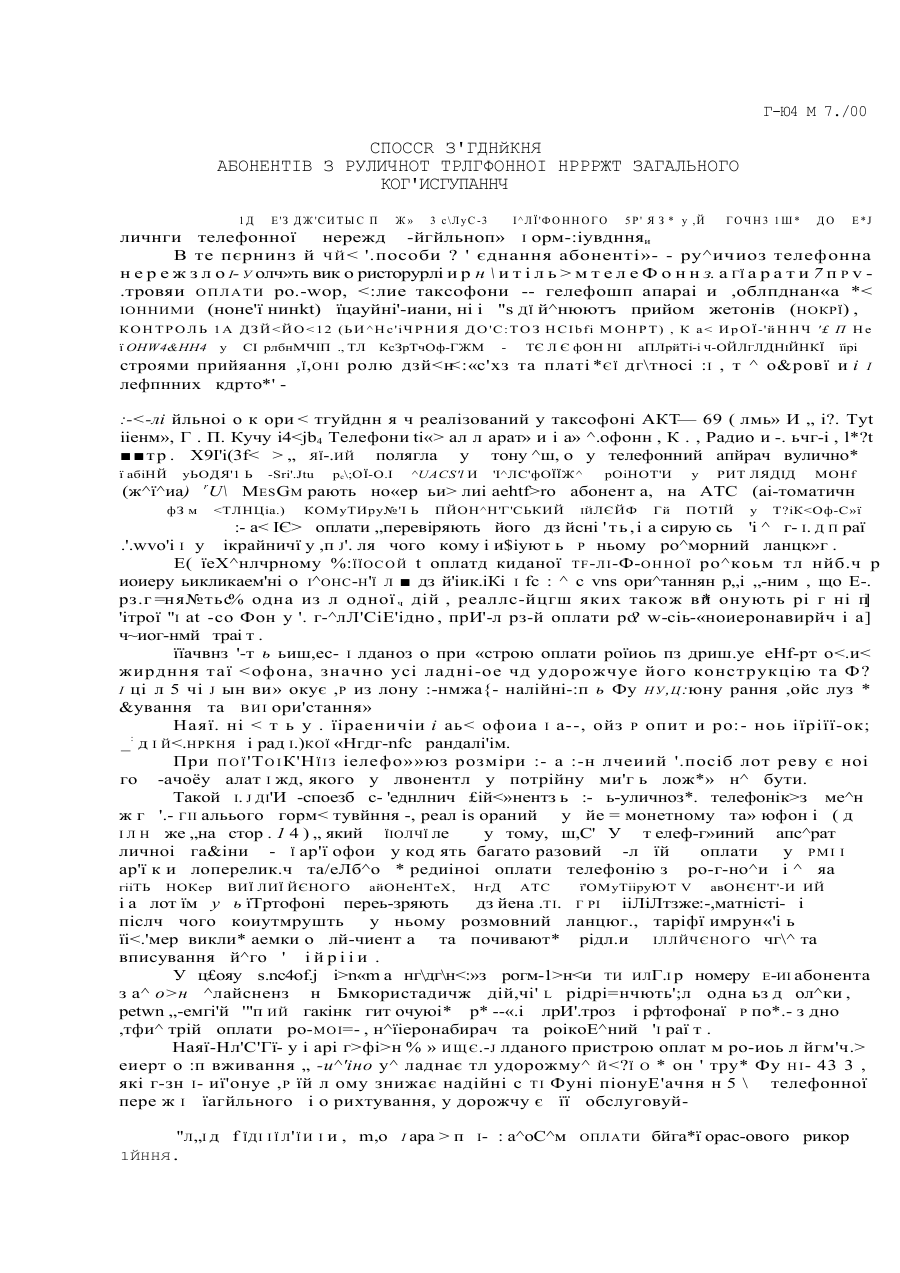
Номер патенту: 31493
Опубліковано: 15.12.2000
Автор: Тугушев Марат Саітович
МПК: H04M 3/00
Мітки: спосіб, телефонної, абонентів, з'єднання, мережі, користування, загального, вуличної
Текст:
Спосіб підключення дощувальних машин позиційної дії до гідрантів закритої зрошувальної мережі
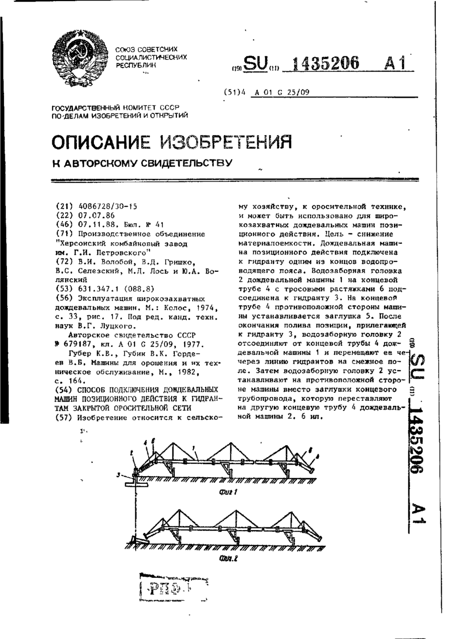
Номер патенту: 5111
Опубліковано: 28.12.1994
Автори: Лось Мирон Давидович, Гришко Володимир Данилович, Селезьський Віктор Сафронович, Волобой Володимир Іванович, Волянський Юрій Олександрович
МПК: A01G 25/09
Мітки: позиційної, закритої, машин, дощувальних, дії, підключення, гідрантів, мережі, спосіб, зрошувальної
Формула / Реферат:
Способ подключения дождевальных машин позиционного действия к гидрантам закрытой оросительной сети, включающий подсоединение трубопровода машины к гидранту одним концом через водозаборную головку, отключение от гидранта после полива, перемещение черезлинию гидрантов и подсоединение другим концом к гидранту, отличающийся тем, что, с целью снижения материалоемкости, после отключения от гидранта водозаборную головку оставляют налинии...
Пристрій підключення дощувальної машини до гідранту закритої зрошувальної мережі
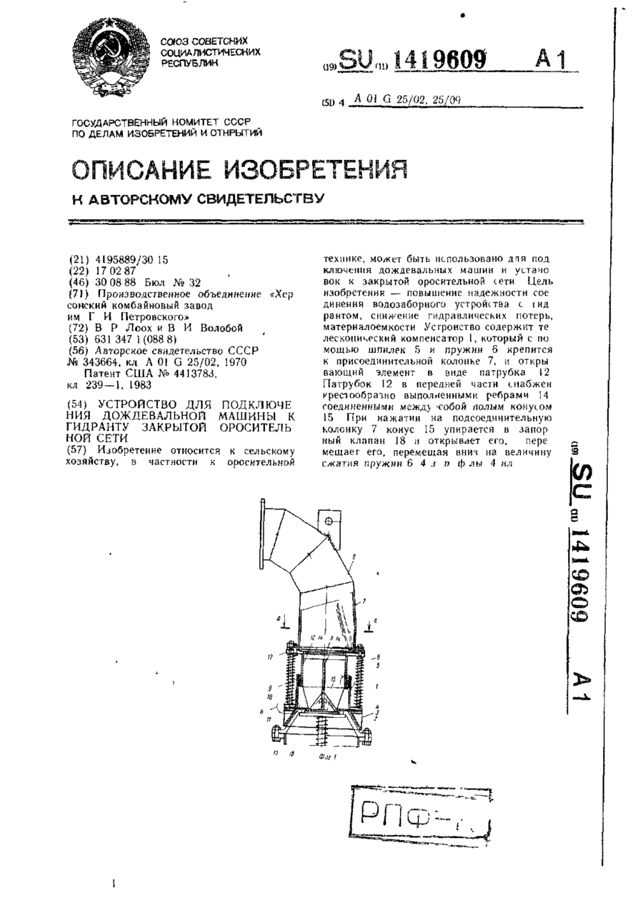
Номер патенту: 5849
Опубліковано: 29.12.1994
Автори: Лоох Владімір Робертовіч, Волобой Володимир Іванович
МПК: A01G 25/02, A01G 25/09
Мітки: гідранту, мережі, підключення, зрошувальної, закритої, машини, пристрій, дощувальної
Формула / Реферат:
1. Устройство для подключения дождевальной машины к гидранту закрытой оросительной сети, включающее подсоединительную колонку с коленом, подпружиненный телескопический компенсатор с направляющим конусом, открывающий элемент, взаимодействующий с гидрантом, жестко связанный с подсоединительной колонкой, обратный клапан и уплотнение отличающееся тем, что, с целью повышения надежности, снижения гидравлических потерь, материалоемкости,...
Пристрій підключення дощувальної установки до закритої зрошувальної мережі
Номер патенту: 6161
Опубліковано: 29.12.1994
Автори: Коваленко Віталій Григорович, Волобой Володимир Іванович, Козачок Борис Дмитрович
МПК: A01G 25/09, A01G 25/06
Мітки: закритої, мережі, дощувальної, зрошувальної, підключення, установки, пристрій
Формула / Реферат:
Устройство для подключения дождевальных установок к закрытой оросительной сети, включающее гидрант с запорным механизмом, подсоединительную колонку и манжетодержатель с уплотняющей лепестковой манжетой, отличающееся тем, что, с целью снижения металлоемкости и повышения надежности работы, гидрант выполнен в виде фланца, имеющего торцовую проточку, а манжетодержатель закреплен на подсоединительной колонке и выполнен с соответствующим...
Попередній патент: Комплексне джерело відновлюваної енергії
Наступний патент: Апарат міхневича о.е. для фіксації стопи в анатомічно правильному положенні
Випадковий патент: Кристалічна поліморфна (+)-(s)-форма гідросульфату клопідогрелю (форма 2) (варіанти), спосіб її отримання (варіанти) та фармацевтична композиція