Вентиль нагрівача
Формула / Реферат
1. Вентиль нагрівача, що має корпус, золотник у вигляді тіла і головки, яка введена в отвір в корпусі, і шток, який проходить крізь заглушку, входить у зазначений отвір і контактує з головкою, який відрізняється тим, що головка (18) конусоподібно збільшується за діаметром після отвору (24) в корпусі.
2. Вентиль за п. 1, який відрізняється тим, що конус (28) простягається до тіла (19).
3. Вентиль за п. 1 або 2, який відрізняється тим, що головка (18) і тіло (19) виконані як одне ціле.
4. Вентиль за п. 3, який відрізняється тим, що головка (18) і тіло (19) виконані як одне ціле литтям під тиском.
5. Вентиль за будь-яким з пп. 1-4, який відрізняється тим, що тіло (19) має зону ущільнення (7), в якій розташоване ущільнююче кільце (21).
6. Вентиль за п. 5, який відрізняється тим, що ущільнююче кільце (21) укладено по периметру тіла (19) у кільцевому пазу (20) і має опору зі зворотного боку.
7. Вентиль за будь-яким з пп. 1-6, який відрізняється тим, що отвір (24) у корпусі переходить у обмежену циліндричною стінкою виїмку (29), а конус на своєму зовнішньому боці має численні виступи (31) з паралельними циліндричній стінці напрямними поверхнями.
8. Вентиль за п. 7, який відрізняється тим, що перехід між отвором (24) у корпусі і виїмкою (29) створений боковою поверхнею конуса (30), причому виступи (31) вище поверхні контакту відповідно скошені.
9. Вентиль за будь-яким з пп. 1-8, який відрізняється тим, що конус (28) має численні напрямні пальці (32), що радіально простягаються в його середину і вільно уведені в порожнину (33), де розташований напрямний штифт (17).
10. Вентиль за п. 9, який відрізняється тим, що напрямний штифт (17) служить упором для пружини (34) стискання, яка навантажує золотник (6) у напрямку заглушки (26).
Текст
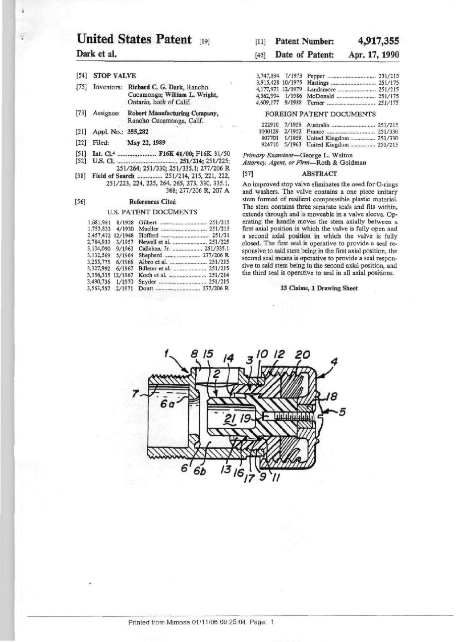
United States Patent [i9] [U] Patent Niunber: [45] Date of Patent: Dark et al. [54] STOP VALVE ^75] Inventors: Richard С G. Dark, Rancho Cucamonga; William L. Wright, Ontario, both of Calif. [73] Assignee; 3,747,894 7/1973 Pepper 3,915.428 10/1975 Hastings 4,177,971 12/1979 Landamore 4,562,994 1/1986 McDonald 4.609,177 9/1988 Turner Robert Manufacturing Company, Rancho Cucamonga, Qalif. [21] Filed: [51] [52] b t . a* U.S. a [58] May 22,1989 F16K 41/00; F16K 31/50 251/214; 251/225; 251/264; 251/330; 251/335.1; 277/206 R Field of Search 251/214,215,221,222, 251/223, 224, 225, 264, 265, 273, 330, 335,1, 368; 277/206 R, 207 A References Cited [56] U.S. P A T E N T D O C U M E N T S 1,681,981 1,753,833 2,457,472 2,784,933 3,104,090 3,132,369 3,255,775 3,327,992 3,356,335 3.490.736 3,563,557 8/1928 4/1930 12/1948 3/1957 9/1963 5/1964 6/1966 6/1967 12/1967 1/1970 2/1971 Gilbert Mueller Hofferd Newell et al Callahan, Jr Shepherd Albro et al Billeter et al Koch et al Snyder Doutt К 251/215 251/215 251/31 251/225 251/335.1 277/206 R 251/215 251/215 251/214 251/215 277/206 R a 15 251/215 251/175 251/215 251/175 25Ї/175 FOREIGN PATENT DOCUMENTS 222910 1000129 807701 924710 Appl. N o . : 355,282 [22] 4,917,355 Apr. 17,1990 7/1959 2/1952 1/1959 5/1963 Australia France United Kingdom United Kingdom 251/215 251/330 251/330 251/215 Primary Examiner—George L. Walton Attorney. Agent, or Firm—Roth & Goldman ABSTRACT [57] An improved stop valve eliminates the need for O-rings and washers. T h e valve contains a one piece unitary stem formed of rcsihent compressible plastic material. The stem contains three separate seals and fits within, extends through and is moveable in a valve sleeve. Op erating the handle moves the stem axially between a first axial position in which the valve is fully open and a second axial position in which the valve is fully closed. T h e first seal is operative to provide a seal re sponsive to said stem being in the first axial position, the second seal means is operative to provide a seal respon sive to said stem being in the second axial position, and the third seal is operative to seal in all axial positions. 33 Claims, 1 Drawing Sheet 1^ 3 10 12 20 б 6b 1316 17 9 'II Pnntedfrom Mimosa 01/11/06 092504 Page 1 US. Patent 4,917^55 Apr. 17,1990 / t івз'Р // f^ > Fig.l Fig.3 FigA ^^^^P^ 13 Fig.5 Printed from Mimosa 01/11/06 09 25 05 Page 2 917,355 2 STOP VALVE FIELD OF THE INVENTION. This invention relates to stop valves and, more partic ularly, to washerless ring seal-less quick acting stop valves for use in water supply lines. BACKGROUND. Stop valves are commonly found in in-line applica tion in the water supply lines to sinks and toilets, water appliances which are normally supplied with water. The valves are usually found under the sink or toilet basin and serve as a convenient manual "shut off. Ac cordingly, the stop valve is nonnaliy always in the open position, permitting water to flow through the plumb ing to the sink faucets and/or toilet basin valve; and are closed only on those infrequent occasions when repairs are to be made to the water appliance. Although several designs for this type of valve are offered in the trade, the most common stop valve construction incorporates 0-rings and/or washers to form a seal and, moreover, consists of as many as eight separate pieces. Though the design is tried and true, the use of so many component parts has obvious cost implications for the manufacturer and ultimately for the customer. Other stop valves of more recent design are formed of a fewer number of parts to reduce cost, as few as three pieces per assembly. These incorporate a thin rubber tubular member that contains a hole in a cylindrical side wall that is rotated to align or mis-aJign the opening with a water passage to thereby open or close the valve. It is designed so that when in the closed position water pressure from the main supply lines enters the hollow of the tubular mem ber forcing the member to radially expand and create a tighter seal. Such recent stop valves are easy to activate and require as little as a quarter turn, 90 degrees, to operate from a fully open to a fully closed position. U.S. Pat. No. 4,562,994 granted Jan. 7, 1986 to MacDonald and U.S. Pat. No. 4,609.177 Sept. 2, 1986 to Turner et al illustrate this kind of valve. Unfortunately it has been learned that some numbers of such valves have been found to leak even when newly installed. While satisfy ing criteria for rninimal component element usage and cost, those three piece type valves do not engender the degree of comfort expected by the trade from the stand point of function, which translates simply as; no water leakage permitted. An object of the present invention is therefore to provide an effective stop valve containing a fewer num ber of component elements than the common design; to produce a stop valve that is of more economical con struction and, when new, does not leak. It is a further object of the invention to provide a stop valve construc tion that does not use O-rings or washers as seals and which allows opening and or closing in as little as a quarter turn of the handle. SUMMARY OF THE INVENTION. An improved quick acting stop valve according to the present invention includes a valve sleeve and a one piece unitary stem formed of a compliant compressible plastic material with the stem including three seals. The stem is fitted within, extends through and is moveable axially in the valve sleeve; and a handle is coupled to the stem. Applying a manual force in one direction to the handle moves the stem and the seals carried thereby axially between a first axial position in which the valve із fully open and a second axial position in which the valve is fully closed and vice-versa when the force is reversed in direction. The first seal is the main valve seal and seals responsive to the stem being in the first 5 axial position, closing the valve; the second seal pro vides a seal responsive to the stem means being placed in the second axial position, furthermost distant from the first axial position, corresponding to the valve being fully open, and the third seal being provides a seal be0 tween the stem and sleeve in all axial positions of the stem. No. " O " rings or washers are required to seal the valve to the sleeve. In accordance with more specific aspects of the in vention the quick acting valve contains as many as five ' parts: the valve body, a valve stem, a sleeve, a handle and a screw with which to fasten the handle to the stem. The stem comprises a one piece elongated generally cylindrical member containing a raised band or rim like portion located at an intermediate position along the stem axis. In turn that band portion contains a lip sur rounding the band portion located at one end thereof to form a forward end or third seal. The lip protrudes outwardly at an inclination to the axis of the stem. In more specific aspects the lip has a right circular conical outer surface and a right circular conical inner surface with the cone angle of the latter being larger than the cortcsponding cone angle of the former. At the other end of the hand portion an annular edge surface is deД fined having a right circular conical surface that serves as a back end or second seal. A central bore or hollow cylindrical cavity wathin the sleeve receives the stem. TTie sleeve bore is of a slightly smaller diameter than outermost diameter of the stem's forward seal portion J to produce a compression between the walls defining the sleeve bore and the stem's forward seal. In accordance with an additional aspect of the inven tion an end wall portion of the sleeve contains a seal seat having an inverted frusta conical surface shape of a } slightly larger cone angle than the cone angle of the stem's inverted cone shaped edge, forming the second seal. That second seal is oriented facing the sleeve seal seat so as to prepare for a mating engagement. With the sleeve being formed of a more rigid material than the j stem, axially pressing the stem against the sleeve wall so that the respective conical shaped portions engage, as occurs when the valve is operated to the full open posi tion, causes the stem edge portion to flare outwardly further and press also against the sleeve bore walls, ) creating a more effective seal. Further the lip portion of the rim or band forming the third seal remains in com pressive contact with the cylindrical sleeve bore walls maintaming a seal there between in all axial positions to which the stem is moved, irrespective of whether or not ) the stem is positioned in the fully operated or fully Opened position. In accordance with a further aspect of the invention, the sleeve attaches to the valve body by a tapered thread that engages a mating tapered thread formed ui ) the valve body surface, the threads being designed to form therebetween an interference fit, creating a sta tionary water tight fourth seal in the same manner as a known standard type plug. In such a combination if the thread in the brass body is a straight thread, then the ) interference fit is attained by the tapered thread on the sleeve. In accordance with a still further aspect of the inven tion, the handle is coupled to the sleeve for rotational Printed from Mimosa 01/11/06 09:25:06 Page: 3 З 4,917,355 4 and axial movement therebetween and is coupled to the larger diameter than the central opening, oriented coaxstem to rotate and аліаііу move the stem. The sleeve ial with the opening in the end wall. The end of the also contains a multi-lead thread on an outer surface, inner wall defming bore 13 has an outward taper 14 that which threads engage a multi-lead thread formed serves as a lead in to permit assembly. The sleeve's end within the inner surface of a depending rim like portion S w^l contains a seal seat 11 that surrounds the central of the handle. This multi-lead thread arrangement alopening and is later described in greater detail. The lows for quick operation of the valve permitting the second smaller cylindrical section of sleeve 3 contains a valve to be fiiUy opened or closed with as little as a tapered outside diameter thread 9 about its outer periphquarter turn of the handle. ery and the sleeves disk like top section contains a multiThe foregoing and additional objects and advantages 10 [gad thread 12, shown at the right side in the figure, of the invention together with the structure charactensthread 9 permits the sleeve to be screwed into place as tic thereof, which was only briefly summarized in the illustrated in the figure within chamber 6b, engaging the foregomg passages, becomes more apparent to those mating threads 10 located on the internal cyhndrical skilled in the art upon reading the detailed description surface of the valve body. Tapered thread 9 is designed of a preferred embodiment, which follows in this sped- 15 ^^ have an interference fit with thread 10. Such profication, taken together with the illustration thereof vides a water tight seal m the same manner as a convenpresented in the accompanymg drawings. jional tapered water type plug. DESCRIPTION OF THE DRAWINGS. S*^"> 2 is of a generally cylindrical shape with front and back cylindrical portions, suitably of slightly differIn the Drawmgs: , , . ,. ^'^ ent diameter, and an annular band-like portion, located FIG. 1 IS a section view of a preferred embodiment ^ between the front and back portions. The band-like with the elements illustrated ш the valve open position; -^^ ^^^^^ ^ cylindrical portion that is larger in FIG. 2 IS a section view of the same embodiment ^.^^^^^^ ^^ ^j^^ diameter of either the cylindrical Illustrated with the elements located m the valve closed ^^ ^^^^^ ^^ ^^^^ ^^^.^^^ ^ ^ ^^^ ^^^^ ^^^ ^^^ ^^^^ ^^^^^j^^ posi ion, . a hollow cylindrical cavity or bore 21, defining a rim or FIG. 3 illustrates in perspective view and to an en,, - / , , . , __„ ,. - „ , „, ^-^ ,,„i.,a ^^^i i s , . , ^, , . J -., • ^. 1. J. annulus 15 that forms the first or mam valve seal 15, larged scale the valve stem used withm the embodiment , ^ . i. j • . j ^ -t -т-і. i n j • ,i. ^ сстг- .. • I -J- Ч 1 .4. I . ,1. . „ laterdescnbedmgreater detail. Those skilled in the art of FIG. 1 mcludmg Its element: the valve seat, the stem t. . j t. .. ->i u • * ^ • i. r J 1 *i, f I *i. 1 * • J *i, recogmze that end chamber 21 may be omitted ш alterforward seal, the stem rear seal, the key section and the • . j-.i. - L L L • m ^ . L^ -1 -](, native embodiments with the chamber space being nlled F I G s \ 5 ^ d б Ulustrates in sectioii and to an en^ І ? '^^^^"^l formhig a solid plug like end to the stem. larged scale the stem and sleeve of the embodiment of ^^ich some may prefer. Stem 2 mcludes a screw hole FIG. 1 in a position of being assembled, full closed P^^age 19 and a keyed section 18 at the nght end. That position and full open position, respectively; and ^eyed section is suitably of a hexagonal shape as better FIG. 7 Ulustrates in partial section view and to an 35 illustrated and dtscussed m FIG. 3. Stem 2 also carnes a enlarged scale a portion of one of the seals used in the «eai 17 defined by an mverted comcal shaped surface embodiment of FIG. 1. ^^ ^ ^ ^ ** formed by a projecting lip, also of conical shape. DETAILED DESCRIPTION. Handle 4 is of an inverted cup-shaped geometry conReference is made to FIG- 1 illustrating a preferred 40 Gaining a top surface and a peripheral rim depending embodiment of the novel stop valve in cross section ^^'^^ '^e top surface The handle top surface includes a view with the valve in open position and to FIG. 2 central axially extendmg opening or slot that is also of a showing the same elements with the valve in the closed hexagonal shape which is sized and keyed to the correposition, which figures may be considered together. spending section of the stem so as to lock or couple the The valve includes a valve body or housing 1, a stem 2, 45 two elements together for joint rotation. Screw 5, suita sleeve 3, a handle 4 and a screw 5. The housing in^^^ІУ ^ self-taping screw, is fastened into place in stem eludes a seal seat 6, formed of an axially extending rim passage 19 and the wide screw head holds the handle in to a circular passage located in wall 6я between an inlet place. As is apparent to those skilled in the art, other opening or bore 7 and a chamber, 6b, located mtermedimeans of coupling or attaching the handle to the stem ate bore 7, bordered by wall 6a, and outlet bore 8 50 may be substituted for the hex key-slot and screw so as formed m the valve housing. A cylindrical opening m to preclude relative rotation between the stem and hanchamber 6b, containing threads 10 formed on the iimer die, such as a threaded hole and bolt arrangement or by surface, serves to receive sleeve 3, in the housing as bonding with epoxy as examples, but the disclosed armore fully discussed hereafter. The valve housing is rangement is preferred. Handle 4 includes a multi-lead suitably of a metal material, suitably brass, fabricated by 55 thread 20 located on a depending rim portion. This conventional technique. Bores 7 and 8 are adapted to be multi-lead thread engages the corresponding lead connected to the respective water supply and water threads 12 on the stem and thereby allows for quick appliance, not illustrated, in a conventional manner. movement of the valve. such as by the threads represented on the outer cylindriThe multi-lead thread may have a very fast pitch, cai surface of the housing portion defming bore 7 and 60 such as two pitches per inch. This allows the valve to the cylindncal opening defming bore 8. open and close in a quarter of a turn. However, if a A sleeve 3 is of a generally cylindrical geometry that slower acting valve were required, a single pitched has a disk like top section, shown to the right in the thread, such as an eight turn per inch thread, could be figure, forming an end wall that contains a centrally substituted and in which case one full turn would be located circular passage or opening; and that also has a 65 required to open or close the valve. As those skilled in second hollow cylindrical section of smaller outer dithe art recognize the handle and multi-lead arrangement ameter than the end wall, with the second cylindrical has served in other valve combinations and serves as section containing a hollow cavity or bore 13 of slightly well as a part of the disclosed valve. Printed from Mimosa 01/11/06 09 25 07 Page 4 4,917,355 Reference is made to FIG. 3 which illustrates in per spective view and to an enlarged scale the valve stem incorporated within the embodiment of FIG. 1. As illustrated the valve stem 2 is of a generally elongated cylindrical shape contains a front cylindrical portion 2a, 5 a back cylindrical section 2b of shghtly smaller diameter than the front and an intermediate band 2c. It includes the front end Seal surface IS shown to the left, suitably tapered at a 45 degree angle; the key section IS of a hexagonal "nut" shape and screw passage 19 shown on 10 the right and the protruding band contains a third cylin drical shaped portion 20. In turn the band contains a ring like lip 16 that protrudes outwardly from and ex tends peripherally about the front cylindrical portion of the stem, the details of which is described in later fig- 15 ures. At the right side the stem member includes a frusta conically shaped edge 17 that serves as a forward seal, extending from the outer surface of the band portion to the surface of cylindrical portion 2b for engaging a seal seat in the sleeve described in greater detail hereafter. 20 handle forces stem 3 to travel from the illustrated posi tion through the sleeve bore to the fully closed sealed position as illustrated in FIG. 2 in which the valve seal surface 15 is pressed against body seat 6. In so doing, the handle and stem are simultaneously moved both axially and rotationally. When the handle is rotated in an anti clockwise from the position illustrated in FIG. 2, stem 2 travels back through sleeve 3 to the full open position, rotating and axially moving. In the full open position, the back end seal 17 of stem 2 engages the sleeve and wall at seat 11. The stem's seal 17 is of an inverted frusta right circu lar conical shape as earlier presented in FIGS. 4 and 5 which is better illustrated in the enlarged partial cross section view of FIG. 4c. The sleeve seal seat 11 also contains an inverted frusta right circular conical shape that is of a larger cone angle, b2, as measured between the taper and the vertical than that of the stem back wards seal 17, angle bl. Hence, in this preferred em bodiment when the seal portions engage, stem edge portion seal 17, being more resilient than the material of For better understanding of the seals carried by stem the sleeve, is forced to flare outwardly against the 2 and the relationship thereof to sleeve 3, reference is sleeve cylindrical bore wall to attain a tighter seal. The made to FIG. 4 that illustrates the two elements to an seal 17 engages the sleeve end wall and, in this preferred enlarged scale in section view with the elements ori ented coaxially prior to assembly of the one within the 25 embodiment, also engages the cylindrical side walls of the sleeve bore. other. For convenience reference may also be made to the corresponding section views of FIG. 5 that shows To the left in FIGS. 2, 4 and 5, sleeve bore 13 con the orientation of two elements following installation tains a lead-in tapered rim portion 14 that allows stem with stem 3 positioned ш a first axial position in which forward seal 16 to enter the sleeve bore along the axis in the valve is closed as in FIG. 2; and to FIG. 6 which 30 being assembled. Stem forward seal 16 is of an inverted shows the two elements with the stem axially moved to right circular conical surface shape and is slightly the second or fully open axial position as in FIG. 1. For flared. It is slightly larger in diameter than the diameter convenience like elements in these additional figures are of sleeve bore 13. When the one is assembled into the denominated by the same reference numerals as in the other, it creates between the two elements an interfer prior figures. 35 ence fit; the stem forward seal 16 is placed under com pression in sleeve bore 13 thus attaining a positive seal. As illustrated in FIG. 4 with the plastic stem in a "relaxed" uncompressed state, the seal lip 16 is formed The valve is mtended to be either in the fully closed of a right circular conical outer surface and a right or fully opened position for the best positive seal and, circular conical inner surface oriented on a common hence, water tightness. Any water pressure exerted axis that intersect or meet along an angle; the cone edge 40 against stem forward seal 16 causes the seal to engage of the latter, a2, being larger than the cone angle, al, of even more tightly against sleeve bore 13, enhancing the the former. Cone angle may be defined as the angle sealing effect. With the valve in the fully closed position made between the cone axis, a straight line from the as illustrated in FIG. 2, the stem's main valve seal 15 is imaginary cone base through the apex and the cone wall forced against body seat 6. Stem back end seal 17 is for a given cone or conical surface or as illustrated the 45 axially displaced from sleeve seal seat 11. Consequently, angle between the sloping surface and the axis of stem 2. sealing between the stem and the sleeve is now main The section formed describes a lip that is inclined rela tained solely by stem forward seal 16, which engages tive to the axis of the stem and sleeve. the inside diameter of sleeve bore 13. Typically in a water installation, the sink pipe is connected to outlet With the lead-bi 14 bemg of any convenient taper, such as a radius of 0.01 inches as example, the stem may 50 bore 8 and contains a small amount of standing water. However, inlet bore 7 is connected to the main water be inserted along the axis of the sleeve into the defined supply lines, which is usually under greater pressure. chamber, from the position illustrated in FIG. 4 to FIG. Seal 16 forms a seal sufficient to withstand the pressure 5, squeezing or compressing the lip. of the standing water and, hence, prevent leakage To assemble the valve, stem 2 is initially inserted through the back end of the stem. Moreover, if the inlet within the sleeve as illustrated in FIG. 5 to couple the 55 pressure increases greatly, the seal between seal portion two elements. The sleeve 2 is then screwed into place 16 and sleeve 3 is enhanced making it even less likely within the valve body. Handle 4 is then screwed over that standing water can escape through the outer pe the sleeve by use of the multi-lead threads and in so riphery of the stem. doing the handle presses against the hex shaped stem end. This allows the hex shaped stem key section to 60 Though containing five elements in total, the valve enter withm the corresponding hex shaped orifice in the includes four seals, three of which are formed in and top of the handle, Self tapping screw 5 is then screwed carried by the stem and are movable: the seal of the into place to hold the handle to the stem. sleeve by the tapered thread to the valve body; the stem forward seal that seals around the sleeve bore; ihe stem When valve 1 is in the normal fully opened position as illustrated in FIG, 1 and handle 4 is turned clockwise to 65 back end seal which engages the sleeve seal seat when the valve is in the full open position; and the stem to close the valve, the multi-lead threads on the handle's front end stem seal which engages the body when the inside rim portion slide within the multi-lead threads 12 valve is in the full closed position. of the sleeve; the turning force or torque applied to the Printed from Mimosa 01/11/06 09:25:08 Page: 5 '-'''-''' 7 8 The handle, sleeve and stem are preferably each What is claimed is: made of a plastic material, each preferably being of a 1. An improved stop valve comprising in combinadifferent polymer. For example, the handle is formed of tion: a valve sleeve and a one piece unitary stem formed a rigid plastic, such as ABS; the sleeve is formed of of resilient compressible plastic material; said valve another rigid plastic material, such as Acetal, that has 5 sleeve containing interior walls defining a passage for the advantage of providing a self-lubricating quality receiving at least a portion of said stem and an end wall that allows the threads to work more smoothly, avoidfor preventing removal of said stem from the end ing binding between the sleeve and handle and also thereof containing said end wall; and said end wall allows the stem to slide more smoothly back and forth containing a passage therethrough; said stem including in the sleeve bore during operation; and the stem is 10 fu-st, second and third seal means, and said stem being made of a more compliant plastic material, such as a fitted within, extending through and movable in said copolymer polypropylene, which allows slight comy^lve sleeve; manual force applying means for moving pression in the seal areas. Acetal also does not absorb said jtem axially between a first axial position in which water. Hence, the integrity of the sleeve dimensions are the valve is fully closed and a second axial position in mamtamed over time. Suitably the three elements are 15 which the valve is fully open; said first seal means being formed by conventional plastic molding processes and operative to provide a seal responsive to said stem aie each unitary one-piece assembUes. means ^^^^ j ^ ggj^ f^st axial position to close the valve The design of the stem and the seals integrally formed ^•^^^ g^^j third seal means being moperative to provide thereon provides a one-picce assembly of novel design ^ ^eal responsive to said stem means bemg in said first and simplifies the construcUon of a stop valve. Labor 20 ^^^ ц-^^. ^ ^ ^^^^^ ^^^j ^ ^ ^ being operative to and parts inventory requirements are reduced. An ad^^^ ^^^ ^1^^^ ^^^ ^^^^^ ^^^l ^^^^^ ^^^ ^^ vantage of the mvenhon is that the stop valve structure j ^ ^ ^ ^^^ ^„^ ^ ^ j ^^^^^ ^j^^^^ responsive to said stem does not require use of any O-rmgs between the stem ^ ^ ^ ^ ^^^^ -^ ^^^ ^^^^^^ ^-^1 -^^^ ^-^j^ ^^^ д^^^ ^d the valve sleeve to attam a water tight seal, al^^^ ^^^„^ inoperative to provide a seal responthough retaming the quahty of bemg quick actmg m 25 ^.^^ ^^ ^^.^ stem means being in said second axial posioperation. Moreover, an addition^ positive seal is pro^^^ ^^^ ^^^^^^ ^^^ ^^^^^ being operative to vided even with the valve m the fully open condition, ., ,^ -j • . n с -j i • n г ^ T^- л ^\. ^ r> • provide a seal to said mtenor walls of said sleeve in all preventmgescapeofwater. Itisalsoseen that noO-nng * . , ^ .. j- -j ^ i. . j • i jj Lais whauoeve? are used in the illustrated embodiment ^^^' positions of said stem between and mcludmg said As those skilled in the art appreciate alternative em- 30 ^"^^^ ^ second axial position. bodiments of the invention may employ different struc^ ^he invention as defined m claim 1 further comtural means to connect the valve stem to the valve body P^'^^S- a valve housing; and means mounting said in a fluid tight relationship other than by use of the «1«^£,"' ^^^^^ relationship to said valve housing, interference fit thread type arrangement or in combina3. The mvention as defined in clann 2 wherem said tion with such kmd of fit without departing from the 35 "^^^^ ^"""^ mounting said sleeve to said valve housing scope of the present invention. comprises: thread means formed on said sleeve and In one practical embodunent of the invention, stem 2 thread means in said housing assembly, with said sleeve is of a length of 1.035 inches, the outer diameter of the t^^^ad means matmgly engagmg said housmg thread front and back cylindrical stem portions were 0.390 and "^^^^ "" ^ interference water tight fit. 0.375 inches, respectively, the diameter of the middle 40 '»• The mvention as defmed m claim 2 wherein each of band was 0.466 inches and the outermost diameter of ^^^ ^^st and third seal means comprises a right circular seal lip 16 was 0Л76 inches. The length of the band was ^^^^ conical surface geometry. 0.130 inches. The stem bore 21 was of a diameter of 5. The invention as defmed in claim 1 wherem said 0.215 inches and the thickness of the annular portion manual force applying means comprises a grippable surrounding bore 21 was 0.070 inches. Further the inner 43 handle coupled to said stem and to said sleeve for simuldiameter of the body seat 6 was 0.350 inches and its taneously rotating and axially moving said stem with midpoint diameter 0.410 inches. respect to said sleeve; and wherein said handle comThe sleeve bore was of a diameter of 0.470 inches, prises an inverted cup like geometry having a top surapprosimately 0.006 inches smaller in tUameter than the ^^^^e and a rim like portion depending from said top sleeve seal 16, and the length of that bore was 0.350 50 surface to defme a cavity; thread means formed in said inches. The stem was moved along the axis from the full inside surface of said rim like portion and extending open position to the full closed position, a distance of about the periphery of said inner surface of said rim like 0.130 inches, which is less than the length of the sleeve portion of said handle; and key slot means extending bore. The sleeve side wall opening 0.400 inches dlamethrough said top surface; and further comprising: couter, which left a clearance with the back cylindrical 55 pling means attaching said handle to said stem to permit portion of the stem. joint rotation of said handle and said stem, said coupling It is believed that the foregoing description of the means comprising: a key and slot means for preventing preferred embodiment of the invention is sufficient in rotation between said handle and said stem with said detail to enable one skilled in the art to make and use the key formed in said stem and engaging said key slot invention. However, it is expressly understood that the 60 means in said handle; and screw means for fastening said details of the elements which are presented for the forehandle to said stem to prevent axial relative movement going enabling purpose is not intended to limit the therebetween. scope of the invention, in as much as equivalents to 6. The invention as defmed in claim 4 further includthose elements and other modifications thereof, all of ing means coupling said handle to said sleeve for rotawhich come within the scope of the invention, become 65 tion and axial movement with respect to said sleeve, apparent to those skilled in the art upon reading this said means comprising: thread means, specification. ThiK the invention is to be broadly con7. The invention as defmed in claim 5 wherein said strued within the full scope of the appended claims. thread means comprises further multi-lead threads, Printed from Mimosa 01/11/06 09:25:08 Page: 6 f I 9 It 4,917 8 The invention as descnbed in claim 1 wherein said valve sleeve IS formed of a relatively ngid incompressi ble non-water absorbent self lubncatmg plastic matenal 9 The invention as defmed m claim 1 wherein said valve sleeve compnses the malenal Acetal, and wherem 5 said stem plastic matenal compnses polypropylene and wherein said valve sleeve compnses the matenal Ace tal 10 The mvention as defmed in claim 1 wherem said stem plastic matenal compnses polypropylene and 10 wherem said valve sleeve compnses the matenal Ace tal 11 The mvention as defined in claim 12 wherein said handle compnses a plastic matenal having a relatively ngid chdractenstic 15 12 The mvention as defined m claim 1 wherem said second seal means compnses a hp, said lip being out wardly protruding and containmg an mverted nght circular conical outer surface and an mverted nght circular conical mner surface with the cone angle of 20 said inner surface bemg larger than the cone angle of said outer surface to defme a taper 13 The mvention as defmed m claim 12 wherem said second seal means compnses a lip, said hp being outwardly protruding and containing an mverted nght 25 ctfcular ccmcal outer surface and an inverted nghl circular corneal inner surface with the cone angle of said inner surface bemg larger than the cone angle of said outer surface to define a taper14 An unproved stop valve compnsmg in combina- 30 tion a valve sleeve; a valve housing, and means mount ing said valve sleeve m sealed relationship to said valve housmg, a one piece unitary stem formed of resilient compressible plastic matenal, said valve sleeve contain mg mtenor walls formmg a passage and an end wall for 35 preventing removal of said stem from the end thereof contaimng said end wall, and with said end wall contammg a passage therethrough, said stem mcludmg first, second and third seal means, and said stem bemg fitted withm, extendmg through and moveable in said valve 40 sleeve, manual force applying means for moving said stem axially between a first axial position ш which the valve is fully closed and a second axial position in which the valve is fully open, said first seal means being opera tive to provide a seal responsive to said stem being in 45 said first axial position to close said valve and with said third seal means bemg inoperative to provide a seal responsive to said stem being in said first axial position, said third seal means bemg operative to provide a seal at said end wall responsive to said stem being in said sec- 50 ond axial position m which said valve is fully open and with said first seal means bemg moperative to provide a seal responsive to said stem bemg m said second axial position, and said second seal means being operative to provide a seal to said mtenor walls of said sleeve m a!J 55 axial positions of said stem between and including said first and second axial positions; wherem said third seal means further compnses an mverted frusta conical sur face geometry, and wherem said valve sleeve contains a seal seat located in said end wall, said seal seat compns- 60 mg a frusta conical geometry, said third seal means being oriented to matmgly engage said seal seat respon sive to said stem bemg in said second axial position, said third seal means having a predetermined cone angle and said seal seat having a cone angle that is larger than said 65 corresponding cone angle of said third seal means 15 The mvention as defined m claim M wherein said second seal means compnses a hp, said Up bemg out wardly protruding and contammg an mverted nght circular conical outer surface and an inverted nght circular corneal mner surface with the cone angle of said inner surface bemg larger than the cone angle of said outer surface to define a taper 16 A umtary valve stem adapted to be installed within and extend through a valve sleeve bore for movement between an open and closed position, com pnsmg in corabmation an elongate one-piece molded member of a resilient compressible plastic material hav ing front and back ends and being of a predetermined length, said member including tubular shaped front and back portions proximate said respective front and back ends and a generally cyimdncal band like portion lo cated m between and coaxial with said front and back tubular portions; said front end of said front portion having a taper defimng a first seal, said band like portion protruding outwardly from the cyimdncal surface of said front and back tubular portions and contammg first and second end edges, with said band like portion being of a height measured along said length thereof that is less than the length of said sleeve bore, said first edge onented toward said front end of said member and defimng a second seal and said second end edge on ented toward said back end of said member to define a third seal, said first edge of said generally cylindrical band like portion defining a tapered hp, with said hp generally radially outwardly projecting from and penpherally extendmg about the surface thereof with the outer diameter of said hp bemg greater, slightly, than the inner diameter of said sleeve bore for producing a compressive force on the walls of said sleeve bore re sponsive to said sleeve being inserted within said sleeve bore, said second edge of said generally cyimdncal member compnsmg a surface having a frusta comcal shape for engagmg at least a portion of the valve sleeve bore to provide a seal when said valve stem is in the open position, and torque coupling means located at said second tubular portion of said member 17 The mvention as defmed in claim 17 wherein said Up is located bordenng said first end edge of said band like portion 18 The invention as defined in claim 17 wherein said third seal means is located within said hp and comprises a conical outer surface on said hp 19 A stop valve compnsmg a valve body, said valve body contaimng an inlet bore, an outlet bore and a chamber with said chamber located intermedi ate said inlet and outlet bores, said chamber includ ing a chamber wall separating said chamber from said inlet bore with said chamber wall containing a passage and a seal seat, with said seal seat bemg located penpheral of said passage, a valve sleeve receiving passage, said valve sleeve receiving passage containmg threads located on an mner surface of said sleeve receiving passage, valve sleeve means, said valve sleeve means including a circular shaped end wall having a circular opening of a first predetermined diameter defmmg an axially extendmg passage with said circular opening being centrally loLdted m said end wall, an axially extending hollow cyimdncal cavity of a second predetermined diameter and length, with said second predetermined diameter bemg greater than the diameter of said circular opening, and Printed from Mimosa 01/11/06 09 25 09 Page 7 11 4,917,355 12 a valve body; a first cylindrical outer peripheral portion with said cylindncal outer peripheral portion containing said valve body containing an inlet bore, an outlet bore threads for matingly engaging said internal threads and a chamber with said chamber located intermedi ate said inlet and outlet bores, said chamber includ of said valve sleeve receiving passage to form an interference fit therebetween; 5 ing; valve stem means; said valve stem means bemg located a chamber wall separating said chamber from said within and extendmg through said hollow cylindrical inlet bore with said chamber wall containing a cavity and said passage in said sleeve means, said passage and a seal seat, with said seal seat being valve stem means comprising: located peripheral of said passage; an elongated one-piece molded member of a com- Ю a valve sleeve receiving passage, said valve sleeve plaint plastic material, with said member having receiving passage containing threads located on an first and second ends and being of a predetermined inner surface of said sleeve receiving passage; length therebetween and including integrally valve sleeve means; therein: said valve sleeve means including: first, second and third seal means located spaced IS a circular shaped end wall having a circular opening from one another along the length thereof with of a first predetermined diameter defining an axi said second seal means being located between ally extending passage with said circular opening said first and third seal means; and being centrally located in said end wall; said sleeve torque coupling means located at said second end means end wall including a seal seat formed about thereof; 20 said sleeve means central opening, said seal seat hand grippable handle means for moving said stem being of a right circular conical shaped surface; means; an axially extending hollow cylindrical cavity of a first coupling means coupling said handle means to said second predetermined diameter and length, with valve stem torque coupling means and second cou said second predetermined diameter being greater pling means rotatably coupling said handle means to 2S than the diameter of said circular opening; and said sleeve means; a first cylindrical outer peripheral portion with said said stem means being responsive to rotation of said cylindrical outer peripheral portion containing handle means in one rotational direction for- axially threads for matingly engaging said internal threads moving in a first direction for permitting said first seal of said valve sleeve receiving passage in said valve means to engage said chamber sealseat to close a 30 body to form an interference fit therebetween; fluid path between said inlet and outlet bores and valve stem means; said valve stem means being located responsive to rotation of said handle means in an within and extending through said hollow cylindrical opposite rotational direction for axially moving said cavity and said passage in said sleeve means, said stem means in the opposite direction to disengage said valve stem means comprising: first seal means from said chamber seal seat to open 35 said fluid path between said mlet and outlet bores and an elongated one-piece molded member of a compli permit said third seal means to engage said end wall ant plastic material, with said member having first of said sleeve means to seal said circular end wall and second ends and being of a predetermined opening when the first seal means is disengaged with length therebetween and including integrally said second seal means being maintamed in sealing 40 therein: engagement with said cylindrical bore wall of said first seal means located at said first end thereof; sleeve means irrespective of the direction of axial second seal means; and movement; and third seal means located spaced from said first end fastener means for fastening said handle means to said thereof and from said second seal means; with stem means. 45 said second seal means located at an position along the length of said member between said 20. The invention as defined in claim 19 wherein said fu'st and second ends; and second seal means comprises: torque coupling means located at said second end a circumfcrentially extending lip for oompressively thereof; engaging said cylindrical walls of said hollow cy lindrical passage in said sleeve means, said lip 50 hand grippable handle means for moving said stem means; formed integrally within said stem and extending in first coupling means coupling said handle means to said a circle of a diameter, DL, with said diameter DL being slightly larger than the inner diameter of said valve stem torque coupling means and second cou hoUow cylindrical cavity of said sleeve means to pling means rotatably coupling said handle means to cause compressive engagement with said walls of 55 said sleeve means; said valve sleeve means upon assembly into said said stem means being responsive to rotation of said valve sleeve means; said lip further including a handle means in one rotational direction for axially right circular conical outer surface of a first cone moving in a first direction to close a fluid path be angle and right circular conical inner surface of a tween said inlet and outlet bores and r«ponsive to second cone angle, with the latter cone angle being 60 rotation of said handle means in an opposite rotational larger than the former cone angle to define a taper. direction for axially moving said stem means in the 21. The invention as defined in claim 20 wherein said opposite direction to open a fluid path between said valve sleeve means includes a radially outwardly ta inlet and outlet bores; and pered edge located at the front end of said hollow cylin fastener means for fastening said handle means to said drical cavity for permittmg said valve stem means to be 65 stem means; more easily received within said hollow cylindrical said first seal means being adapted to engage said valve cavity. body seal seat means to prevent fluid from passing 22. A stop valve comprising: between said inlet bore and said outlet bore respon Printedfrom Mimosa 01/11/06 09.25 10 Page 8 ,355 - sive to said stem means being located in a first axial position, whereby said valve is closed; said third seal means being adapted to engage said seal seat of said end wall of said sleeve means responsive to said stem means being located at a second axial 5 position furthermost opposite said first axial position, whereby leakage is prevented when the valve is open; and said second seal means being adapted to engage said cylindrical bore wall of said sleeve means cavity at Ю every axial position of said stem means between and including said first and second axial positions to assist in preventing leakage when the valve із at least par tially open. 23. The invention as defined in claim 22 wherein said IS sleeve means comprises a water nonabsorbent self lubri cating relatively rigid plastic material; said plastic mate rial being less compliant than said material of said stem means. 24. The invention as defined in claim 22 wherein said 20 sleeve means material comprises Acetal. 25. The invention as defined in claim 22 wherein said stem means comprises a compressible material and wherein said valve sleeve means comprises a relatively rigid materia!, said material being more rigid than said 25 stem means material; wherein said third seal means includes a frusta conical surface; and wherein said frusta conical shape of said third seal means of said stem means is of a first cone angle and said frusta conical shape of said seal seat in said valve sleeve means is of a second 30 cone angle, with said second cone angle being greater than said first cone angle, whereby said third seal means is forced to flare outwardly responsive to pressing axiaUy directed engagement of said stem means with said sleeve means seal seat. 35 26. The invention as defmed in claim 25 wherein said threads of said cylindrical outer peripheral portion of said valve sleeve means comprises a first predetermined pitch; and wherein said sleeve means further mcludes: a second cylindrical shaped outer peripheral portion lo- 40 cated adjacent said first cylindrical outer peripheral portion, with said second cylindrical shaped peripheral portion containing threads of a second predetermined pitch; and wherein said second predetermined pitch is less than said first predetermined pitch. 45 27. The invention as defined in claim 28 wherein said handle means includes a rim portion and wherein said second coupling means comprises thread means located on an internal surface of said handle rim portion for matingly engaging said thread means of said second 50 cylindrical shaped outer peripheral portion of said sleeve means. 28. A unitary valve stem adapted to be installed within and extend through a valve sleeve bore of diame ter D and an axial length L for movement between an 55 open and closed position, comprising: an elongate one-piece molded member of a resilient compressible plastic material, said elongate mem ber including: first and second ends and being of a predetermined 60 length, LI; first and second generally cylindrically shaped portions of respective diameters D l and DIB; and a third portion located between and adjacent said 65 first and second cylindrical portions, said third portion including a cylindrical shaped section having a second predetermined diameter, D2, 14 where D2 is slightly larger than the diameter of said first and second cylindrical portions, to de fine a raised band, and said third portion being of a predetermined length L2, where L2 is less than H; said third portion defining first and second annular edges at the first and second ends, said edges respectively, bridging the outer surface thereof to the surface of said respective adjacent first and second cylindrical portions; said third portion further including a lip located bordering said first edge thereof, with said lip outwardly projecting from and peripherally ex tending about said surface coaxial with said first cylindrical shaped portion to form a seal surface, said lip having a right circular conical outer surface and with the outer diameter of said lip, D3, being greater slightly than D2 and being slightly greater than said D, the inner diameter of said sleeve bore, whereby a compressive force is produced between said lip and said sleeve bore responsive lo said stem being installed in said sleeve bore; said second annular edge being oriented facing toward said second end of said member with said second annular edge having an inverted frusta conical shape to define a seal surface for engag ing at least a portion of the valve sleeve bore to provide a seal when the valve stem is in the openposition; said first cylindrical portion including an end surface forming a seal surface; and said second end of said member including torque coupling means for coupling a torque thereto. 29. ТЪе invention as defined in claim 28 wherein said lip further comprises an inverted right circular conical inner surface with the cone angle of said inner surface being greater than the cone angle of said outer surface. 30. The invention as defined in claim 28 wherein said torque coupling means comprises a key of hexagonal shape. 31. The invention as defined in claim 30 wherein said member further includes a first passage, said first pas sage extending a predetermined distance from said sec ond end with said first passage being adapted to receive a fastener means. 32. A stop valve comprising: a valve body; said valve body containing an inlet bore, an outlet bore and a chamber intermediate said inlet and outlet bores, said chamber including: a chamber wall separating said chamber from said inlet bore with said chamber wall containing a passage and a seal seat, with said seal seat being located peripheral of said passage; a valve sleeve receiving passage spaced from said inlet and outlet bores with said valve sleeve receiv ing passage containing internal threads; sleeve means; said sleeve means being formed of a relatively rigid non water absorptive slippery plastic material and includ ing: a circular shaped end wall having a circular opening of a first predetermined diameter, DW, defining an axially extending passage with said circular open ing being centrally located in said end wall; Printed from Mimosa 01/11/06 09:25:11 Page: 9 between said lip and said sleeve bore cavity respon said end wall including a seal seat bordering said sive to said stem bemg located within said sleeve opening, said seal seat being of a nght circular cavity, conical surface shape, an axially extending hollow cylindrical cavity of a said first cylmdncal portion mcludmg an annular edge second predetermined diameter, DC, and of a 5 at said first end of said member, said annular edge length. LC, said second diameter DC being greater having a tapered shape to form a seal for engagmg than the diameter DW of said circular opening, and said seal seat in said chamber wall, and a cyhndncal shaped penpheral outer surface portion said second end of said member including coupling with said cylmdncal shaped outer surface penph means for coupling a torque thereto, eral portion contammg a first thread for matmgly 10 hand gnppable handle means for turning said stem engaging said internal threads of said valve sleeve means, said handle means having coupling means for receiving opening in said housing and forming an coupling to said valve stem torque coupling means interference fit therebetween, and preventing relative rotational movement therebe valve stem means, compnsmg tween, said handle means mcludmg a top surface and a annular nm pomon dependmg from said top sur an elongate one-piece molded member of a resilient 13 face, said handle means nm portion contaimng a mul compressible plastic matenal, said elongate member ti-lead thread on an inner surface thereof, including first and second ends and being of a predetermmed said multi-lead thread on said handle means nm portion length, LS, bemg Ш operative mating engagement with said mul first and second generally cylmdncally shaped por- 20 ti-lead thread on said sleeve means, whereby rotation of said handle means causes said handle means to tions of diameter DSl and DS2, respectively, and move axially of said sleeve means, a third band portion, located between and adjacent said first and second cylmdncal portions, said third said stem means bemg responsive to rotation of said portion including a cyhndncal section being of a handle means m one rotational direction for axially diaineter, DS3, where DS3 is slightly larger than 25 moving within said hollow cavity in a first direction said diameter DS2, to define a raised band portion, to move said annular edge of said first cylindrical and said third band portion being of a predeter portion into sealing engagement with said seal seat in mined length LB, where LB is less than LS, said chamber wall and close a fluid path between said said third band portion definmg first and second an inlet and outlet bores and bemg responsive to rotation nular edges bndgmg the top and bottom ends, te- 30 of said handle means ш an opposite rotational direc spectively, of the outer surface thereof to said re tion for axially moving said stem means in the oppo spective adjacent first and second cylmdncal por site direction to withdraw said first seal means from tions, contact with said seal seat in said chamber wall to said first annular edge facmg toward said second end open a fluid path between said mlet and outlet bores and having an inverted frusto conical shape to 35 and for moving fu-st annular edge of said third cyhn defme a seal surface for engagement with said seal dncal portion of said stem means mto engagement seat of said sleeve means; with said seal seat in said sleeve means wall to pro said second annular edge mcludmg a Up, with said lip duce a scalmg engagement therebetween and with outwardly projecting from and penpherally ex said lip of said third cylmdncal portion maintaining tending about said first cylmdncal portion, said lip 40 sealmg engagement with the walls of said sleeve having a nght circular corneal shaped outer surface means hollow cyhndncal cavity, and and an mverted nght circular shaped inner surface screw means for fastemng said handle means to said with the cone angle of said inner surface being stem means greater than the cone angle of said outer surface 33 The invention as defined in claim 32 wherein the and with the outer diameter of said lip, LL, being 45 diameter of said first cyhndncal portion of said stem is greater slightly than DS3 and being shghtly greater greater than the diameter of said second cylmdncal than Sdid DS, the inner diameter of said sleeve portion of said stem bore, whereby a compressive force is produced * * * * * SO 55 60 65 Printed from Mimosa 01/11/06 09 25 11 Page 10 - 14 Patent Clairas 1. Radiator valve having a housing, a closing element, which comprises a head part and a body, and a tappet, which passes through a stuffing box and lies adjacent to the head part that projects into a housing bore, into which also the tappet projects, characterised in that the head part (18) widens conically beyond the diameter of the housing bore (24). 2. Valve according to claim 1, characterised in that the cone (28) extends as far as the body (19). 3. Valve according to claim 1 or 2, characterised in that the head part (18) and the body (19) are of one-piece construction. 4. Valve according to claim 3, characterised in that the head part (18) and body (19) are together in the form of an injection moulded part. 5. Valve according to any one of claims 1 to 4, characterised in that the body (19) has a sealing zone (7) in which a sealing ring (21) is arranged. 6. Valve according to claim 5, characterised in that the sealing ring (21) is inserted in a groove (20) on the circumference of the body (19) and is supported at its rear side. 7. Valve according to any one of claims 1 to 6, characterised in that the housing bore (24) - 15 continues as an opening (29) which is bounded by a cylinder wall, and the cone (28) has on its outside several projections (31) having guide surfaces directed parallel to the cylinder wall. 8. Valve according to claim 1, characterised in that the transition between the housing bore (24) and the opening (29) is in the form of a conical envelope (30), the projections (31) being correspondingly angled above the guide surface. 9. Valve according to any one of claims 1 to 8, characterised in that the cone (28) has inside it several radially inwardly directed guide fingers (32), which leave free a central space (33) into which a guide pin (17) built into the housing projects. 10. Valve according to claim 9, characterised in that the guide pin (17) acts as support for a compressionspring (34) which biases the closing element (6) towards the stuffing box (26), Патентний повірввні (реєстр. ї* ЗО) ^^ \ Я. Крилоеа • Іяви^їяоп-йматнітвП * -^ Fig.l Fig. 2 - 1Padiator valve The invention relates to a radiator valve navmg a housing, a closing element/ which comprises a head part and a body, and a tappet, which passes through a stuffing box and lies adjacent to the head part that projects into a housing bore, into which also the tappet projects. It may be necessary from time to time to replace the stuffing box of such radiator valves, for example, because after a number of movements of the tappet the stuffing box becomes worn and leaky. To prevent a relatively large amount of water from escaping from the heating circulation during this replacement, it is known in the case of the Applicant's radiator valves to arrange a seal m a circumferential groove m the head part, the seal having a larger diameter than the housing bore. If the stuffing box is now unscrewed, under the action of a spring acting m the opening direction on the closing element and, if desired, also under the action of the pressure of the heating liquid, this seal bears against a housing end face which surrounds the housing bore, and thus seals off the housing bore. When a new stuffing box is screwed m , the head part is pressed inwards again, and the seal lifts away from the housing end face. In that case, however, the stuffing box has already taken over the sealing function again. This additional sealing function of the head part has proved effective m many cases. A closing element of such a construction is relatively difficult to - 2manufacture, however. Firstly, the head part has to be machined in order to provide a seat and a support for the seal. Secondly, the seal has to be mounted on the head part during assembly. The invention is based on the problem of simplifying manufacture. In a radiator valve of the kind mentioned in the introduction, that problem is solved m that the head part widens conically beyond the diameter of the housing bore. There is thus no longer any need for a seal which is intended to prevent escape of heating liquid when replacing the stuffing box. On the contrary, this function is now performed by the head part itself. When the closing element is pressed away from the valve seat, the conical widening comes to bear against the edge of the housing bore and forms a seal there. Since the seal is no longer effected by a two-dimensional engagement of a seal against an end face, the risk of a leak occurring as a result of any tilting is also less. On the contrary, the cone of the head part is applied over its entire circumference, with the necessary pressure, against the axial edge of the housing bore. An edge thus meets a surface. Since the material of the head part will in many cases be somewhat softer than the material of the housing, the housing can here, if appropriate, dig into the head part a little. An excellent seal is achieved as a consequence. This applies also when the axial edge of the housing bore is not sharp-edged, but bevelled or rounded somewhat. Even \ I - з then, the respective surface pressures that occur between the housing and the head part are large enough for a satisfactory seal to be achieved. The sealing effect is also achieved, however, when the material of the head part is as hard as or even harder than the material of the housing. Moreover, the construction has a further advantage: since the seal is no longer in the form of a separate component, in the event of faulty operation this seal cannot be washed away by escaping water, which would impair the operability of the radiator valve. Such a situation occasionally occurs where the differential pressures are large. As there is no longer a separate seal, this problem does not arise. The seal can no longer come out of the valve. The cone preferably extends as far as the body. The cone, that is, the conical widening of the head part, then not only takes over the actual sealing function during removal and insertion of the stuffing box, but also transfers to the body the forces exerted by the tappet on the closing element. It is hereby relatively easy to achieve on the one hand a relatively large diameter of the closing element and the associated valve, and on the other hand to prevent to a large extent the occurrence of moments between the head part and the body. A relatively stable closing behaviour of radiator valve is therefore achieved. In an especially advantageous practical form, the head part and the body are of one-piece construction. This facilitates assembly. Only a single part has to be handled. - 4Particularly when head part and body are together in the form of an injection moulded part, manufacture of the valve can be quite significantly simplified. Further preparation of the closing element is then only necessary to a very slight extent, if at all, and can in most cases be completely avoided. The body advantageously has a sealing zone in which a sealing ring is arranged. The sealing ring then lies adjacent to the valve seat. Only there is it necessary for the sealing function to be fulfilled. The sealing material can therefore be restricted to an annular region in the sealing zone. The remaining parts of the closing element can be made of other materials, especially harder materials, which have a greater stability against deformation. It is no longer necessary to make the entire closing element of the sealing material or to cover it therewith. The sealing ring is preferably inserted in a groove on the circumference of the body and is supported at its rear side. The groove holds the sealing ring in place. The body supports the sealing ring at the same time at its rear side, that is, at the side remote from the valve seat, so that the required closing forces can be transferred to the sealing ring. The housing bore preferably continues as an opening which is bounded by a cylinder wall, the cone having on its outside several projections having guide surfaces directed parallel to the cylinder wall. With this practical form the closing element can be centred in relation to the housing bore in which the cylindrical - 5end of the head part engages. This facilitates assembly, because the closing element is automatically brought into the correct alignment without additional manipulation. Because merely projections are provided, friction between the closing element and the housing can be kept low. This makes for a high reliability of the valve combined with minimal structural complexity. An adequate number of projections has to be provided, of course. For preference, at least nhree projections are used. An arrangement with four projections has also proved effective. In that case it is especially preferred for the transition between the housing bore and the opening to be in the form of a conical envelope, the projections being correspondingly angled above the guide surface. The area with which the projections can be secured to the cone is therefore enlarged. The construction of the cone with projections therefore becomes more stable. In an especially preferred practical form, provision is made for the cone to have several radially inwardly directed guide fingers, which leave free a central space into which a guide pin built into the housing projects. This guide pin is preferably of cylindrical construction. It is fixedly positioned in the housing. This need not mean that it is part of the housing. It may also have been fixed in the housing by auxiliary means. By this arrangement the position of the closing element m the housing is additionally stabilised. On the one hand, this enables the closing element to be guided more precisely m relation to the valve seat. In the present case it is nevertheless at least equally - 6important that the additional sealing function of the cone can then be fulfilled with great reliability, because the guide p m is providing the appropriate guidance. The guide fingers can also be of plate-like construction, that is, can be m the form of triangles, if appropriate with projections, so that an improved stability of the closing element on the guide ring is achieved. This guidance is then effected m the axial direction always with a certain longitudinal extension. In that case it is especially preferred for the guide p m to act as support for a compression spring which biases the closing element towards the stuffing box. The spring IS then supported by the guide fingers of the closing element, and is therefore unable to escape laterally. This is mainly relevant to assembly. In operation the spring ought not to touch the guide fingers, at any rate not over their length, but at the end. When the stuffing box is removed, the spring presses the cone directly against the housing. The invention IS described hereinafter with reference to preferred exemplary embodiments m conjunction with the drawings, m which: Fig, 1 shows a first embodiment of a radiator valve Fig. 2 and shows a second embodiment of a radiator valve as an angle valve. A radiator valve 1 comprises a housing, which is formed by a housing body 2 and a housing cover 3. An inlet connection 4 and an outlet connection 5 are provided m the housing body 2. The flow path between the inlet
ДивитисяДодаткова інформація
МПК / Мітки
МПК: F16K 13/00
Код посилання
<a href="https://ua.patents.su/132-46022-ventil-nagrivacha.html" target="_blank" rel="follow" title="База патентів України">Вентиль нагрівача</a>
Вентиль

Номер патенту: 13240
Опубліковано: 28.02.1997
Автор: Малков Віктор Іануарович
МПК: F16K 1/00
Мітки: вентиль
Формула / Реферат:
Вентиль, содержащий корпус с седлом, крышку, размещенный в корпусе запорный орган в виде тарелки, прикрепленной к концу шпинделя посредством соединительного элемента, отличающийся тем, что на конце шпинделя выполнен кольцевой бурт, запорный орган снабжен уплотнением установленным со стороны седла, соединительный элемент выполнен в виде втулки, диаметр которой равен диаметру тарелки, а во втулке со стороны запорного органа выполнена расточка...
Універсальний вентиль для перекриття абразивних потоків
Номер патенту: 33882
Опубліковано: 15.02.2001
Автори: Дячишин Мирон Михайлович, Примоленний Юрій Васильович, Тарабаринов Петро Васильович, Боднар Володимир Михайлович, Пазяк Микола Михайлович, Бульбас Валерій Миколайович, Меркур'єв Анатолій Борисович
МПК: E21B 34/00
Мітки: абразивних, потоків, універсальний, вентиль, перекриття
Текст:
...стійкість до корозії та абразивного зношення, тобто не порушується цілісність поверхні кулі під дією потоків абразивних частинок (наприклад, піску) при високих тисках і швидкостях. Виготовлення внутрішнього діаметра корпусу по діаметру кулі запобігає биттю кулі об стінки корпуса. Внутрішня поверхня корпуса виготовлена із застосуванням карбонітрації, що значно збільшує поверхневу твердість та абразивостійкість. Ущільнення сідла, яке виконане...
Вентиль балону для стиснених газів
Номер патенту: 11463
Опубліковано: 25.12.1996
Автори: Чиркунов Володимир Миколайович, Дробець Володимир Арсеньович, Борейша Ігор Вікторович, Дімант Давид Рувимович, Штукаріна Світлана Євгенівна
МПК: F16K 31/60
Мітки: газів, балону, стиснених, вентиль
Формула / Реферат:
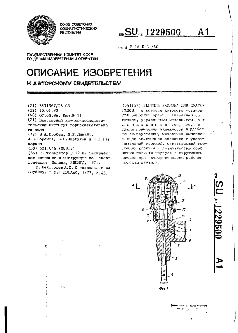
Вентиль баллона для сжатых газов, в корпусе которого установлен запорный орган, связанный со штоком, управляемым маховичком, отличающийся тем, что, с целью повышения надежности и удобства эксплуатации, маховичок выполнен в виде эластичной оболочки с уплотнительной кромкой, охватывающей горловину корпуса с возможностью сообщения полости корпуса с окружающей средой при разгерметизации рабочей полости вентиля.
Шихта для виготовлення нагрівача пристрою високого тиску
Номер патенту: 20283
Опубліковано: 15.07.1997
Автори: Виноградов Сергій Олександрович, Доценко Василь Михайлович, Терентьєв Сергій Олександрович, Івахненко Сергій Олексійович
МПК: B01J 3/06
Мітки: виготовлення, нагрівача, високого, тиску, пристрою, шихта
Формула / Реферат:
Шихта для изготовления нагревателя устройства высокого давления, содержащая электропроводный и теплоэлектроизоляционный материалы, отличающаяся тем, что линейные размеры частиц теплоэлектроизоляционного материала не менее, чем в 4 раза превышают линейные размеры частиц электропроводного материала при следующем соотношении компонентов шихты (мас.%):Электропроводный материал 10-30...
Пристрій попереднього підігріву рідкого палива для нагрівача мобільної машини
Номер патенту: 5563
Опубліковано: 28.12.1994
Автори: Адольф Шодт, Фрітц Морінг, Петер Райзер
Мітки: пристрій, нагрівача, машини, підігріву, палива, попереднього, мобільної, рідкого
Формула / Реферат:
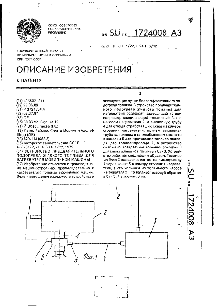
1. Устройство предварительного подогрева жидкого топлива для нагревателя мобильной машины, в частности автомобиля, содержащее подводящий топливопровод, одним своим концом соединенный с топливным насосом, связанным с камерой сгорания нагревателя и установленным непосредственно на нагревателе, а другим своим концом - с топливным баком, и выхлопную трубу для отвода отработавших газов из камеры сгорания нагревателя в атмосферу, отличающееся...
Попередній патент: Регульований подільник потоку рідини
Наступний патент: Покрівельний матеріал, який здатний до пластичного деформування вручну
Випадковий патент: Ангоб