Посуд для приготування страви
Номер патенту: 46766
Опубліковано: 17.06.2002
Автори: Сабакар Олексій Іванович, Борисевич Володимир Карпович, Зорік Володимир Якович
Формула / Реферат
1. Посуд для приготування страви, який включає корпус, кришку із оболонкою обтічника, приєднані до них ручки і розташовану усередині корпусу на увігнутостях пластину, який відрізняється тим, що між пластиною та увігнутостями розміщено клапан для екранування інгредієнтів страви, що готується, від киплячої рідини та конденсату при рухах їх відносно корпусу, котрий виконано у вигляді пружного кільця, яке притискує до корпусу верхню крайку звислої з увігнутостей юбки з матеріалу густиною, меншою густини рідини, а на кільці виконані грибоподібні напливи з боку пластини, між якими заведені виступи з неї, а на периферійній ділянці оболонки обтічника виготовлені у бік кришки виступи з просіченою і відвернутою до середини стінкою для розділення потоків пари та конденсату та усунення попадання останнього на страву, що готується, крім цього кришка і корпус сполучені байонетним з'єднанням для попередження викидання назовні страви, що готується, причому у відбортовці кришки утворені виступи із ущільнювачем, а у відбортовці краю корпусу виконані вибірки.
2. Посуд по п. 1, який відрізняється тим, що на пластині розташовано ємність із судками для одночасного приготування декількох страв, яка розділена на дві ділянки перетинкою з відвернутими у різні боки від неї косокутними пелюстками при спиранні їх на відбортовку ємності, причому в одній ділянці ємності по середині відбортовки зачіплено за неї судок одним боком подвійного крючка, а в другій ділянці підвішені два судки із таким же фіксуванням кожного на кут 30°, утворений між площиною перетинки та площиною, що проходить через середину перетинки та бік крючка судка, при цьому на пластинці виконано увігнутості для центрування ємності, а на периферійній ділянці оболонки обтічника вмонтовано через отвори у ній із пружного матеріалу грибки із утворенням кутів 120° між ними.
3. Посуд по одному з пп. 1-2, який відрізняється тим, що зверху до кришки приєднано відкритий із периферійного боку карман для розміщення столового набору, в котрому поміщено фіксатор у вигляді пластини із відвернутим краєм у бік та на виході із кармана, яку установлюють осями своїми, паралельними відвороту на другому краї, на кронштейни через зазори, утворені між внутрішньою поверхнею кармана та відкритими кінцями крючків кронштейнів, причому в пластині виконані увігнутості під розміщені збоку кармана пружини та рельєф із випуском рукояток набору із кармана.
4. Посуд по одному з пп. 1-3, який відрізняється тим, що між розташованою усередині корпусу пластиною та його дном змонтовано теплоелектронагрівач для автономного використання посуду, який підключено до електричної мережі через блок живлення та стабілізатор струму з вбудованим таймером.
5. Посуд по одному з пп. 1-4, який відрізняється тим, що до ручки кришки прилаштовано крючок, вільний кінець якого досягає ділянки увігнутості у корпусі, а поверхні, стичні з киплячою рідиною, покриті плівкою із матеріалу з малою адгезійною здатністю, наприклад із тетрафторетилену.
Текст
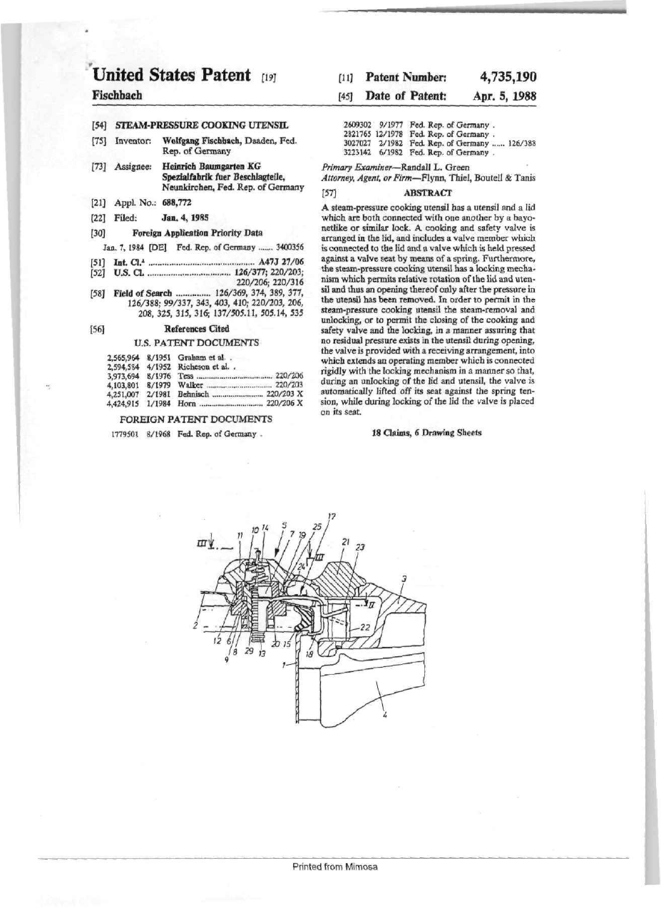
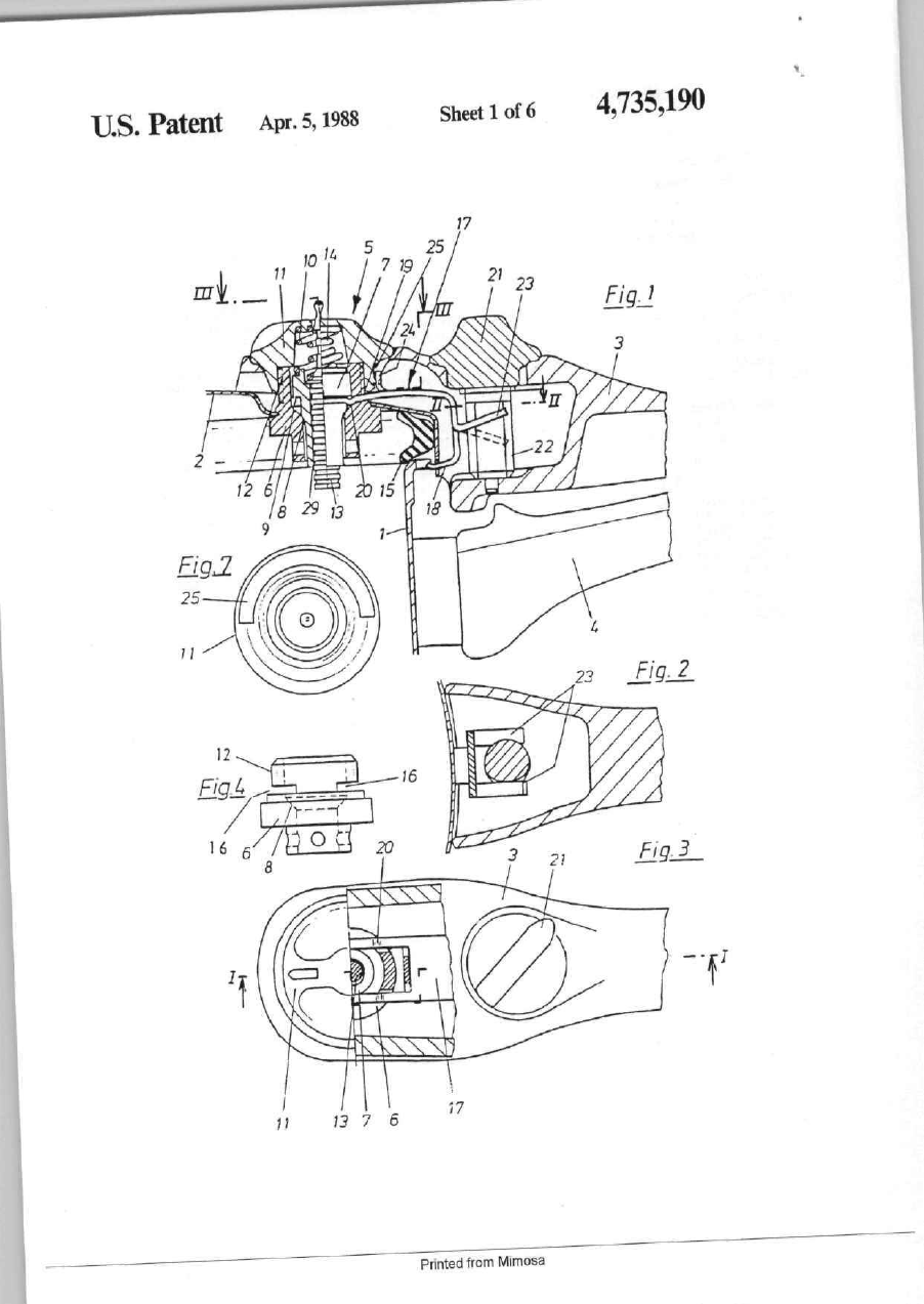
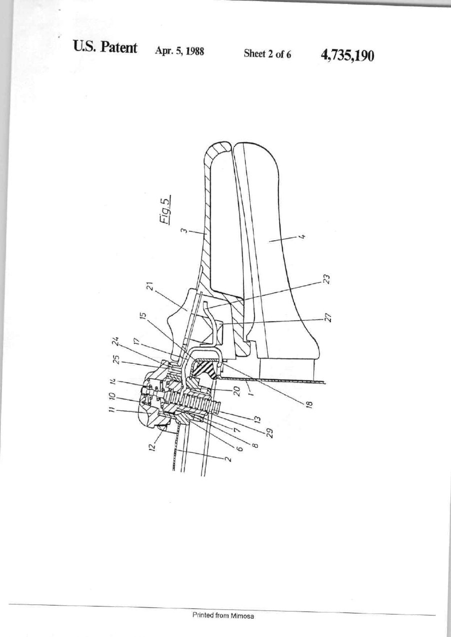
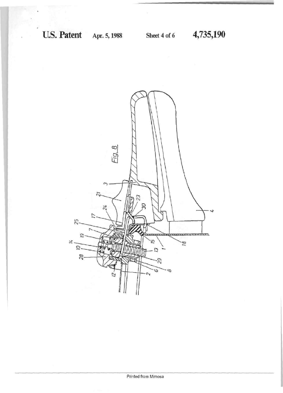
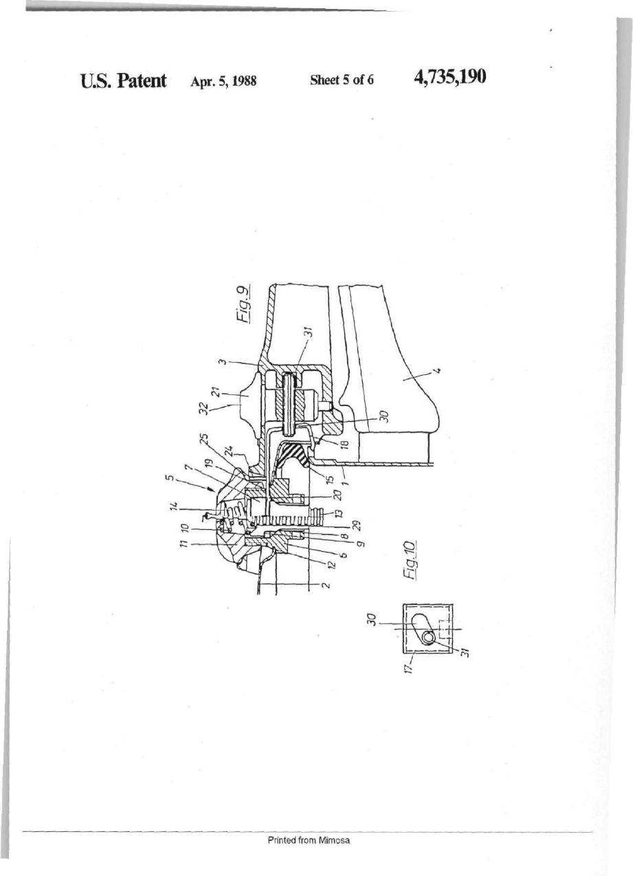
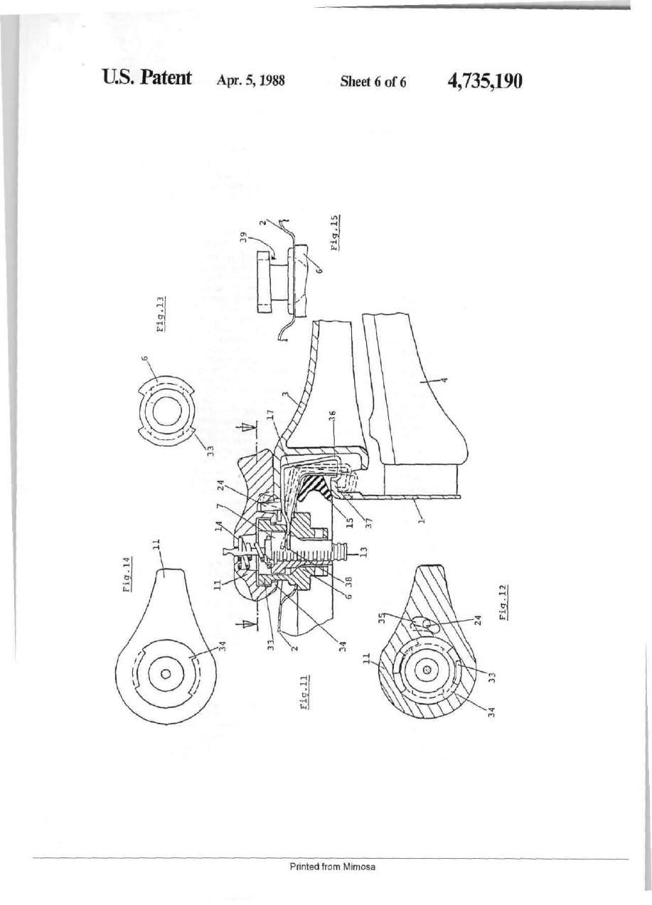
United States Patent m [11] Patent Nmnber: 4,735,190 Fiscbbach [45] Date of Patent: Apr. 5,1988 2609302 2821765 3027027 3223142 [54] SreAM-PHESSURE COOKING UTENSIL [75] Inventor: Wolfgang Fischbach, D^den, Fed. Rep. of Germany [73] Assignee: Heimicfa Bflmagartea KG Spezialfabrik Aier Bescblagteile, Neunkirchen, Fed. Rep. of Germany [21] Appl. No.; 688,772 [22] Filed: [30] Jan. 4,1985 Foreign Application Priority Data Jan. 7. 1984 p E ] Fed. Rep. of Gemany 3400356 [51] b t . a . * [52] U.S. CL A47J 27/06 126/377; 220/203; 220/206; 220/316 [58] Field of Search 126/369, 374, 389, 377, 126/388; 99/337, 343, 403, 410; 220/203, 206, 208, 325, 315, 316; 137/505.11, 505.14, 535 {56) References Cited U.S. PATENT DOCUMENTS 2,565,964 8/1951 Graham et al. . 2,594,584 4/1952 Ricfaeson et a!. . 3,973,694 8/1976 Tess 4,103,801 8/1979 Walker 4,251.007 2/1981 Behnisch 4,424.915 1/1984 Horn 220/M3 220/203 X 220/206 X FOREIGN PATENT DOCUMENTS 1779501 8/1968 Fed. Rep. of Germany 2Z0/206 9/1977 12/1978 2/1982 6/1982 Fed. Rep. of Germany . Fed. Rep. of Germany . Fed- Rep. of Germany Fed. Rep. of Germany . 126/388 Primary Examiner—Randall L. Green Attorney, Agent, orFirm—Flytm, Thiel, Boutell & Tanis ABSTRACT [57] A steam-pressure cooking utensil has a utensil and a lid which are both connected with one another by a bayonetlike or similar lock. A cooking and safety valve is arranged in the lid, and includes a valve member which is connected to the lid and a valve which is held pressed against a valve seat by means of a spring. Furthermore, the steam-pressure cooking utensil has a locking mecha nism which permits relative rotation of the lid and uten sil and thus an opening thereof only after the pressure in the utensil has been removed. In order to permit in the steam-pressure cookmg utensil the steam-removal and unlocking, or to permit the closing of the cooking and safety valve and the locking, in a manner assuring that no residual pressure exists in the utensil during opening, the valve is provided with a receiving arrangement, into which extends an operating member which is connected rigidly with the locldng mechanism in a manner so that, during an unlocking of the lid and utensil, the valve is automatically lifted off its seat against the spnng ten sion, while during locking of the lid the valve is placed on its seat 18 Clainu, б Drawing Sheets Printed from Mimosa U.S. Patent Apr. 5,1988 sh^tiof6 4,735,190 ligJ Fm- 3 -ТІ • f Pnnted from Mimosa U.S. Patent Apr. 5,1988 Sheet 2 of 6 Printed from Mimosa 4,735,190 U S . Patent Apr. 5,1988 Sheet 3 of 6 Pnnted from Mimosa 4,735Д90 u s . Patent Apr. 5,1988 Sheet 4 of 6 Pnnted from Mimosa 4^35,190 U.S. Patent Apr. 5,1988 Sheet 5 of б Pnnted from Mimosa 4,735,190 U.S. Patent Apr. 5,1988 гм"^\ t r 1—^ k tb 1 1 Sheet 6 of 6 in ^^ r і v. к •H 1_ . Printed from Mimosa 4,735,190 4,735,190 breakdown during operation, so that breakdowns in operation must be expected in the long run. A basic purpose of the mvention is to suggest a steampressure cooking utensil of the above-mentioned type FIELD OF THE INVENTION which has a cooking and safety valve and a locking Thb iDvention relatK to a steam-pressure cooking mechanism in which the steam removal and unlocking utensil and, more particularly, to a cooking utensil in or the closing of the cooking and safety vavle and the which the utensil and lid are connectd with one another locking is done with an operating button, wherein it is by a bayonetlike or similar lock, which includes in the assured that no residual pressure can remain in the utenlid a cooking and safety valve having a valve member j ^ ^^^ ^ ^ ^^-^^^ -^ basically simple in design and thus connected to the lid and a valve pressed against a valve inexpensive to manufacture and also is reliable in opera seat by a spring, and which includes a locking mecha tion in the long run. A further purpose involves permitnism which permits a rotating of the Ud and utensU and tmg removal of the safety valve only after the lid has thus an opening thereof only after the pressure m the been removed from the utensil. utensil has been removed. 15 SUMMARY O F THE II4VENTION BACKGROUND OF THE INVENTION This purpose is attained by providing a cooking uten Certain food which is to be cooked is cooked in sil of the above-mentioned type in which the valve has steam-pressute cooking utensils under an excess pres a receiving arrangement, mto which extends aa operat sure inside of the steam-pressure cooking utensil, so that 20 ing member which is cotmected rigidly to the locking mechanism so that, upon an unlocking of the Ud and the steam-pressure cooicing utensil must be provided utensil, the valve is lifted off automatically from its seat with a safety valve which, at a specific excess pressure, against the spring tension, and so that upon locldng of vents steam and thus lowers the pressure in the cooking the lid, the valve is placed onto its seat. utensil. Thus, the locking pin which effects the locking of the It is known to combine the safety valve with a cook- 25 utensil and lid is, in the inventive steam-pressure cook mg valve, wherein the spring tension which presses the ing utensil, connected to an operating member which valve against its valve seat can be varied to adjust for directly engages the valve and, during movement of the the different cooking stages. This valve thus works as a locking mechanism into the locking positin, lifts the regulating valve and keeps the pressure in the cooking utensil at a predetermined value. It is furthermore 30 valve off its valve seat against a spring tension, so that an antomatic ventilation of the steam-pressure cooking known to also provide such a cooking and safety valve utensil occurs. Since the valve is lifted from its valve with a cooking indicator, namely a piston which is lifted seat, it is also assured that no residual pressure remains against a spring force in dependence on the pressure in to the steam-pressure cooking utensil. On the other the steam-pressure cooking utensil and which thus indi cates with its markings the level of the pressure in the 35 hand, it is also assured by this that pressure in the steampressure cooking utensil can only build up after the lid steam-pressure cooking utensil. and utensil are closed with one another and the locking Such a steam-pressure cooking utensil is operated at a mechanism is moved into the locking position. high pressure, which means that care must be taken that The operating member for the valve, which operat the steam-pressure cooking utensil cannot be opened 40 ing member is connected to the locking mechanism, is under pressure. This safety measure also serves to pre either a seesaw or a slide member and, in the simpliest vent pressure from building up in the steam-pressure case, is a U-shaped sheet-metal strip with a longer leg cooking utensil when the lid and utensil are not cor and a shorter leg. The shorter leg serves to lock the rectly closed. As a safety measure, a locking pin is pro utensil and lid together, while the longer leg engages vided which can be moved into the bayonet lock of the the receiving arrangement of the valve. This receiving lid and utensil, so that in this position relative rotation of 45 arrangement can mclude slots which are mounted later the lid and utensil is no longer possible. ally on the valve, or an annuiar recess. If the operating It is known from German Ofienlegungsschrift No. 17 member is a slide member, the end of the longer leg is 79 501 to extend the control button for the adjustment provided with a bending or bent section or the like so that, during movement of the operating member ap of the initial tension for the safety and cooking valve 50 proximately perpendicular to the direction of move and thus for the individual cooking stages, and to let the ment of the valve, the operating member is automati extended end, duriog its turning movement into the cally lifted or lowered, depending on whether ventila cooking stage, cooperate with a locking pin which is tion is supposed to take place or pressure is supposed to moved downwardly against a spring force and th\is causes a locking or rather a release of the utensil and lid. 55 be built up. The shorter leg engages the bayonet be tween the utensil and lid and is moved together with the We are dealing here with a one-button automatic, in other leg so that, on the one hand, a release occurs which only Ш the ventilacion position of the safety during ventilation and, on the other hand, a locking of valve can the locking pin permit opening through rota the utensil and lid occurs prior to the pressure buiid-up tion of the lid on the utensil. This also assures that the safety valve can only be closed when the steam-pressure go and lowering of the valve. cooking utensil was properly closed with its bayonet A plate is constructed on the operating member for lock, namely when the recess in the utensil edge for moving the operating member, which plate cooperates receiving the locking pin lies exactly under the pin. This with an adjustment knob which moves the operating known solution thus offers safety features against an member correspondingly. When the operating member unintended opening and closing of the steam-pressure 65 is a seesaw, the shorter leg is lowered during the opera tion of the adjustment knob, so that it disengages from cooking utensil, but this one-button automatic is also the bayonet of the utensil and the lid, while the front very complicated and thus, on one hand, expensive to end of the longer leg, which engages the receiving manufacture and, on the other hand, susceptible to STEAM-PRESSURE COOKING UTENSIL Printed from Mimosa f^A th , 35,190 4 arrangement of the valve, is lifted, wherein the pivot FIG. 1 is a fragmentary longitudinal sectional view of point is provided on the upper leg at a location spaced a part of a steam-pressure cooking utensil which has a from the receiving arrangement of the valve. cooking and safety valve and a locking mechanism According to a further suggestion of the invention, which embody the invention; the lowering can also be done by means of a rotatable FIG. 2 is a sectioiml view taken along the line II—II button which is provided with a screw thread, wherein 5 of FIG. 1; the plate of the operating member engages the threads FIG. 3 is a sectional view taken along the line Шof the screw member. The plate is advantageously di - I I I of FIG. 1; vided in two, so that it engages both sides of the screw FIG. 4 is a view of a valve member of the cookmg thread. Furthermore, a nose is arranged on the longer leg of 10 and safety valve of FIG. 1; FIG. 5 is a fragmentary sectional view similar to the operating member, which nose lies on the side FIG. 1 which illustrates a further exemplary embodi which does not face the lid and cooperates with the ment according to the invention ш which the operating rotatable button for the adjusting of the initial tension of member, as in FIG, 1, is constructed as a seesaw; the spring of the valve, that is with the rotatable button which adjusts for the cookmg stages. A groove is pro ^^ FIG. 6 is a fragmentary sectional view similar to FIG, 1 which illustrates a further exemplary embodi vided for this purpose in the rotatable button, into ment of the invention having an operating member which groove extends the nose of the operating member which is constructed as a slide member; when it is in the closed position. The rotation of the FIG. 7 is a bottom view of a control button which is rotatable button is limited by this, that is it can only be turned in the region of the cooidng stages, whereby it is ID a component of the embodiments of FIGS. 5 and 6; assured that an unintended tunung of the rotatable but FIGS. 8 and 9 are fragmentary sectional views similar ton out of the cooking position is prevented, which to FIG. 1 which illustrate two further exemplary em otherwise would result in the steam being able to escape bodiments according to the invention; in an explosionlike manner from the utensil. FIG. 10 is a front view of an operating member and a According to a further suggestion of the invention, bushing which are components of the embodiment of the shorter leg of the seesaw is formed so that, in the И О . 9; cooking position, it carries out the lock but, m the vent FIG. II is a fragmentary sectional view similar to ing position, rests already on the utensil wall so that a FIG. 1 which illustrates a further exemplary embodifurther swinging of the seesaw is prevented by the uten, sil wall. The nose which is formed on the balance then 2Д ment according to the invention, in which the control button takes over the function of the operating button of " extends into the groove which is constmcted in the the preceding embodiments; -rotatable button, so that removal of the control button FIG. 12 is a sectional view taken along the Ime XII." and thus the valve from the lid is prevented when the lid • is still secured on the utensil. An unintended release of —ХП of FIG. 11; 35 FIG. 13 is a top view of a valve member which is a the valve from the utensil is prevented by this. component of the embodiment of FIG. 11; According to a further suggestion of the invention, FIG. 14 is a bottom view of a control button of which " t h e operating button can be eliminated, wherein the is a component the exemplary embodiment according to -' control button for holding the valve takes over the task irof the operating button. A control groove is arranged FIG. 11; and Г :for this purpose in the control button, into which con- 4Q FIG. 15 illustrates an alternative embodiment of a . rtrol groove extends the nose which is formed on the valve member of the embodiment of FIG. 11 which is seesaw. Upon rotation of the control button, the dis built into the lidtance of the nose from the axis of rotation of the control DETAILED DESCRIPTION button is changed, whereby the seesaw is lifted or low 45 The steam-pressure cooking utensil which is illus ered, depending on whether a switch from the venting trated in FIG. 1 includes a utensil 1 and a Ud 2. A handle position hito the cooking position or vice versa is sup part 4 is mounted on the utensil 1, and a handle part 3 is posed to take place. The shorter leg of the seesaw is mounted on the lid 2- The closing position of the lid 2 advantageously constructed here so that it rests in the and utensil 1 is reached when both handle parts 4 and 3 venting position on an outer wall of the utensil and thus 50 lie one on top of the other. prevents a further rotation of the control button, which A cooking and safety valve 5 is provided in the lid 2. assures that an unintended release of the valve is pre The safety valve 5 includes a valve member 6 and a vented. Only after the lid has been removed from the valve 7 which is arranged movably therein. The valve utensil can the control button be further rotated, namely 7, in the illustrated position, rests on a seat 8 of the valve into the position in which it is removed from the valve 53 member, so that no steam can escape from the inside of seat. The connection of the control button and valve the steam-pressure cooking utensil. The valve 7 is held seat occurs advantageously through a bayonet connec in this position by a biasing spring 10, wherein the tion formed on the valve seat and the control button, so spring initial tension is adjusted by a control button 11, that a removal of the control button from the valve seat which is screwed onto an external thread 12 of the is possible only in the release position. 60 valve member 6. The valve 7 is provided with a bore 29, in which a Further advantageous developments of the invention pressure iniiicator 13 is supported for movement against will become evident in connection with the description the urging of a spring 14. When pressure has built up and drawings. inside of the steam-pressure cooking utensil, the presBRIEF DESCRIPTION OF THE DRAWINGS 65 sure indicator 13 is lifted so as to project further from the control button 11, wherein the magnitude of the Seven exemplary embodiments of the invention will pressure in the steam-pressure cooking utensil is indi be described in greater detail hereinafter in connection cated by rings on the pressure indicator, with the drawings, in which: Printed from Mimosa :,190 6 A seal 15 is inserted in a conventional manner into the utensil is assured by a Ufting of the valve, and the con edge of the lid 2, and seals off the utensil and hd with struction is substantially simpler. respect to one another. In the exemplary embodiment accordmg to FIG. 5, A recess in the form of a pair of slots 16 is arranged similar parts are provided with the same reference nu in the valve 7, through which slots extend two longer merals used above. In this exemplary embodiment, the legs 19 of an operating member 17, wiiich legs act onto operating member Js again a seesaw which pivots about a shoulder 9 of the valve 6. The operating member is a point 20. The plate 23 which is connected to the oper U-shaped in a side view, and has a shorter leg 18 and a ating member 17 is constructed slightly arc-shaped and longer leg 19 connected by a bight. The shorter leg 18 extends through a guideway 27 in the operating button serves at the same time as a locking member and en 1 21. The curvature of the plate is adapted to the direction gages the bayonetiike lock between the utensil 1 and lid of the path of movement of the operating button 21 such 2. This prevents in a conventional manner relative rota that, upon sliding movement of the operating button to the right in the drawing, a lowering of the plate 23 and tion of the lid and utensD. thus a release movement of the locking member 18 and The operating member 17 is constructed as a seesaw, on in other words is pivotally supported and pivots with і a lifting of the valve 7 occurs. Upon movement of the operating button 21 in the opposite direction, the valve its longer leg 19 about a point 20. An operating button is again lowered onto its valve seat 8 and the locldng 21 is used to pivot the operating member 17, which member 18 engages the bayonet lock of the lid and button 21 is constructed as a control button in the exem utensil, so that relative rotation of lid and utensil is plary embodiment according to FIG. 1 and is arranged I impossible. On the other hand, the operatmg member 17 in the upper handle part 3. The operating button 21 has can be moved forwardly only when the utensil and lid a screw thread 22, the threads of which are engaged by Ue correctly one above the other, that is are closed a plate 23 which is connected to the bight of the operat correctiy, otherwise the locking member 18 of the oper ing member 17. The plate 23 is divided into two spaced ating member 17 hits a projecting part of the bayonet parts (FIG. 2) and engages on both sides the threads of lock. The result in such a situation is that the valve 7 is the screw 22. Rotation of the operating button 21 causes not lowered and pressure thus cannot build up in the the plate 23 and thus the operating member 17 to pivot steam-pressure cooking utensil. about the pivot point 20, wherein during a downward In the exemplary embodiment which is illustrated in movement of the plate the valve 7 is lifted from its seat FIG. 6, similar parts are identified with the same refer 8 and the locking member 18 disengages from the bayo ence numerals used above. This exemplary embodiment net lock of the utensil and lid. In reverse, during upward differs from the two preceeding ones m that the operat movement of the plate 23, a locking of the utensil and ing member 17 is constructed as a slide member. The lid and a lowering of the valve 7 onto its seat 8 is operating member 17 is moved by an operating button achieved. The shoulder 9 in the valve 7 is thereby de 21, into which the plate 23 extends form-locking] y. The signed sufficiently large so that, when the valve is low front end of the longer leg 19 is provided with a bent ered, it can operate m a normal manner as a cooking and section 28. The position illustrated in FIG. 6 is the cook safety valve. ing position, namely, the valve 7 is lowered onto its valve seat 8 and the locking member IS locks the utensil A nose 24 is arranged on the longer leg 19 of the and lid against relative rotation. If the utcasil is to be operating member 17 and swivels together with the opened, then the operating button 21 is moved from the operating member. The nose cooperates with a groove illustrated position to the right, wherein the bent section 25 in the control button 11, wherein the groove extends 28 grips under the atmular shoulder 9 of the valve 7, circumferentially less than 360° in the control button 11. which causes the valve to be lifted off from its seat 8 and This assures that the control button 11, when the valve the pressure in the utensil to be completely removed. 7 is closed and the utensil is locked, can be rotated only The locldng member simultaneously release the utensH for a specific angular amount to change the initial ten and lid, so that the utensil can subsequently be opened sion of the spring 10 and thus the adjustment of the without any danger of injury due to hot steam. individual cooking stages. On the other hand, this pre vents the control button 11 from bemg turned off сога^ In the exemplary embodiment which is illustrated m pietely so that, during an excess pressure Іа the steamFIG. 8, similar parts have the same reference numerals pressure cooking utensil, the valve 7 is ejected up- ; used above. The operating member 17 is also con wardly. structed in this exemplary embodiment as a seesaw. The The operating member 17, of which an integral part is difference between this exemplary embodiment and the the locking member 18, thus is made of a U-shaped exemplary embodiment according to FIG. 5 substan piece of bent sheet шеіаі and can be manufactured inex tially mvolves the plate 23 being connected fixedly to pensively. Moreover, an automatic coupling of the ; the operating button 21 and engaging a guideway 30 which is provided in the operating member 17. The valve position and the locking is achieved through this, shape of the guideway and the shape of the plate 23 are wherein the operation is done by a control button, as is adjusted to one another so that, during movement of the illustrated in FIGS. 1 and 3, or by a push button 21, as operating button 21 to the right in FIG. 8, a lowering of is illustrated in FIG. 5. In the exemplary embodiment according to FIG. 1, like thai according to FIG. 5, the ( the shorter leg 18 and a lifting of the longer leg 19 occurs, which causes on the one hand the lid and utensil operating member 17 is constructed as a seesaw. If one to be unlockai and on the other hand the valve 7 to be compares the inventive steam-pressure cooking utensil lifted off from its seat S. and its safety mechanism with conventional pressure cooking utensils with their extremely complicated In the exemplary embodiment according to FIGS. 9 safety mechanisms, which are susceptible to trouble, f and 10, similar parts have the same reference numerals used above. The operating member 17 is also con then it becomes apparent that both have the same func structed as a seesaw and pivots about the pivot point 20. tions, but in contrast to the known ones it is also assured An operatmg button 21 is used to pivot the operating that a residual ventilation of the steam-pressure cooking Printed from Mimosa 7 4,735, 190 member 17, and the operating button 21 is constructed as a control button and can be rotated about a vertically lying axis 32 in the handle part 3. A bushing or pin 31 extends perpendicular witti respect to the axis 31 through the operating button 21, and engages a guideway or slot 30 in the operatmg member 17. The guideway 30 is inclined with respect to the direction of move ment of the bushing 31 (FIG. 10) so that, upon rotation of the operating button 21, the oper^ing member 17 is lifted or lowered, with the result that the utensil is locked and the valve 7 released, or the utensil is un locked and the valve 7 is lifted off from its seat 8. In the exemplary embodiments according to FIGS. 11to 14, similar parts have the same reference numerals used above. The difference between the exemplary embodiments accordmg to FIGS. 11 to 14 and the pre vious embodiments is that the operating button 21 is omitted and the function of the operating button is performed by the control button 11. A further differ ence is that the fastening of the control button 11 on the valve member 6 is not effected by a screw thread, but by a bayonet lock 33 and 34, wherein the fastening position and the release position are arranged with respect to one another such that a rotation of the control button 11 in the locking and also the steam release position is easily possible without any danger of a release of the control button 11 and the valve member 6. Moreover, a further rotation of the control button 11 in the locking position can exist, namely when with the cam control button different cooking positions are supposed to be possible. In this case, cam plates 39 are constructed on the valve member and, during rotation, permit a ten sioning or relaxing of the spring 14. The nose 24 on the operating member 17 engages a guide groove 35 , which is constructd in the control button 11 so as to cause the distance of the nose 24 from the pivot point of the control button 11 to change dur ing the rotation. This results in a swivelling of the oper ating member 17, as is illustrated with one solid-line position and two dashed-line positions ш FIG. 11. The cooking position is represented by the solid-line position of the operating member 17. The end 36 of the operat ing member 17 engages here the edge of the utensil 1, so that the utensil 1 and hd 2 arc locked against rotation relative to one another. When the cooking operation is to end, the operating button 11 is rotated and moves the member 17 so that the end 36 grips under the edge 37 of the utensil 1, as shown in the upper dashed-line position of the operating member 17. The front end 38 of the operating member 17 is lifted at the same time, which causes the valve 7 to be lifted off from its valve seat and the venting operation to start. A further rotation of the control button 11 to a position in which the valve 7 can be removed is not possible, bacause the end 36 prevents a fiirther rotation. Only during a pressureless condition, when the lid 2 has been removed from the utensil 1, can the control button be further rotated until the end 36 of the operating member 17 assumes the position which is illustrated in the lower dashed-lme position in FIG. 11. The bayonet lock between the valve member б and control button 11 can be released m this position and the valve can be removed for cleaning. This additional function of the lock for the removal of the valve from a Hd which is mounted on the utensil is possible in a similar manner in the exemplary embodi ments with a separate operating button 21. Care must only be taken here that the nose 24 comes out of the 8 5 '"^ '^ ,„ 35 ^ 45 50 55 60 65 groove 25 of the control button 11 only after the lid and utensil are separated. Although particular preferred embodiments of the invention have been disclosed in detail for illustrative purposes, it will be recognized that variations or modifi cations of the disclosed apparatus, including the rear rangement of parts, lie within the scope of the present invention. The embodunents of the invention in which an exclu sive property or privilege is claimed are defined as follows 1. A steam-pressure cooking utensil in which the utensQ and lid are connected by a bayonetlike or similar lock, comprismg a cooking and safety valve which is arranged in the hd and has a valve member which is connected to the lid and a valve which is urged toward a valve seat by a biasing element, and a locking mecha nism which permits a rotating of the lid and utensil and thus an opening thereof only after the pressure in the utensil has been removed, wherein the v^ve is provided with receiving means into which extends an operating member which is comiccted rigidly to the locking mechanism so that, upon an unlocking of the lid and utensil, the valve is lifted automatically from its seat against the urging of the biasing element, and so that, upon locldng of the lid, the valve is placed onto its seat, and wherein the operating member is substantially Ushaped, has a short leg which is a part of the locking mechanism, has a longer leg which engages the receivuig means on the valve, and has a bight which connects the short leg and the longer leg. 2. A steam-pressure cooking utensil according to claim 1, wherein the receiving means on the valve in cludes laterally arranged slots which lie above the valve seat. 3. A steam-pressure cooking utensil according to claim 1, wherein the cooking and safety valve includes a pressure indicator. 4. A steam-pressure cooking utensil according to claim 1, wherein the locking mechanism can prevent relative rotation of the lid and utensil through direct engagement with the bayonetiike lock, wherein the receiving means on the valve includes at least one slot which receives the longer leg of the operating member, and wherein the shorter leg of the operating member is the locking mechanism. 5. A steam-pressure cooking utensil according to claim 1, wherein the biasing element is a helical com pression spring. 6. A steam-pressure cooking utensil according to claim 1, wherein the operating member is a seesaw and has a pivot point in the region of the longer leg. 7. A steam-pressure cooking utensil according to claim 6, mcluding a bushing or plate which engages the bight of the operating member and can be moved by means of an operating button. 8. A steam-pressure cooking ulensU according to claim 7, wherein the operating button is constructed as a rotatable control button, and wherein the bushing is arranged in the control button is arranged perpendicu lar to its axis of rotation and engages an inclined guideway provided in the operating member. 9. A steam-pressure cooking utensU according to claim 7, wherein the operating button is constructed as a slide member and the plate is slidably received in a guideway in the operating button or a guideway in the operating member. Printed from Mimosa 9 4,735, 190 10. A steam-pressure cooking utensil according to claim 7, wherein the operating button is constructed as a control button having a screw thread which is engaged by the plate. 11. A steam-pressure cooking utensil according to claim 10, wherein the plate is forked and engages opposite sides of the thread of the control button. 12. A steam-pressure cooking utensil according to claim 1, wherein the operating member is constructed as 10 a sUde member, and wherein a front end of the longer leg, which cooperates with the valve, is provided with a bent section, reinforcement or the like which, during movement of the operatmg member, cooperates with a shoulder of the receiving means of the valve so that the valve is lifted or lowered. 13. A steam-pressure cooking utensil according to claim 12, wherein an adjustment knob engages a plate of the operating member and causes, directly or through 20 eccentncs, movement of the operating member. 14. A steam-pressure cooking utensil according to claim 1, wherein the biasing element is a spring, mcluding a nose which Is arranged on the operating member and cooperates with a groove in a movable control button which adjusts an initial tension of the spring of the cooking and safety valve, wherein when the valve is closed and the utensil and lid are locked, the nose cooperates with ends of the groove to limit movement of the 30 10 control button and thereby limit the initial tension of the spring to values appropriate for cooking. 15. A steam-pressure cooking utensil according to claim 14, wherein an end of the operating member is formed so that, in the steam-removal position, the end rests on the wall of the utensil, and wherein the nose in this position extends into the groove in the control button. 16. A steam-pressure cooking utensil according to claim 1, wherein the biasing element is a spring, and wherem a control button is connected to the valve member by a further bayonet lock, the control button supporting an end of the spring which is remote from the valve. 17. A steam-pressure cooidng utensil according to claun 16, wherein a nose is guided in an arcuate guide groove which is constructed in the control button and which lies eccentrically with respect to the pivot axis of the control button. 18. A steam-pressure cooking utensil according to claim 16, wherein the further bayonet lock permits rotational movement of the control button relative to the valve member and includes cam plates which are provided on the valve member and which engage the control button, wherein as the control button is rotated relative to the valve member the cam plates effect axial movement of the control button relative to the valve member and thereby vary an initial tension of the spring. * * « * * 33 60 6S Printed from Mimosa
ДивитисяДодаткова інформація
Автори англійськоюSabakar Oleksiy Ivanovych, Borysevych Volodymyr Karpovych, Zorik Volodymyr Yakovych
Автори російськоюСабакар Алексей Иванович, Борисевич Владимир Карпович, Зорик Владимир Яковлевич
МПК / Мітки
МПК: A47J 27/00
Мітки: посуд, приготування, страви
Код посилання
<a href="https://ua.patents.su/12-46766-posud-dlya-prigotuvannya-stravi.html" target="_blank" rel="follow" title="База патентів України">Посуд для приготування страви</a>
Посуд для приготування страви
Номер патенту: 21919
Опубліковано: 30.04.1998
Автори: Зорік Володимир Якович, Сабакар Олексій Іванович, Борисевич Володимир Карпович
МПК: A47J 27/00
Мітки: посуд, приготування, страви
Формула / Реферат:
1. Посуда для приготовления пищи, включающая корпус, крышку, прикрепленные к ним ручки и пластину внутри корпуса, отличающаяся тем, что к крышке присоединен обтекатель для отвода конденсата к корпусу, который выполнен в виде обращенной к крышке выпуклостью куполе-образной оболочки, помещенной внутрь корпуса с кольцевым зазором относительно внутренней поверхности стенки корпуса, а сбоку корпуса вблизи его днища выполнены пуклевки, на...
Посуд для приготування страви
Номер патенту: 46784
Опубліковано: 17.06.2002
Автори: Борисевич Володимир Карпович, Зорік Володимир Якович, Сабакар Олексій Іванович
МПК: A47J 27/00
Мітки: посуд, страви, приготування
Формула / Реферат:
Посуд для приготування страви, який включає корпус, кришку з обтічником, приєднані до них ручки та внизу корпусу на увігнутостях пластину, який відрізняється тим, що в ділянці крайки обтічника по периметру в стінці корпусу виконані отвори нижче рівня верхньої крайки оборки, змонтованої своєю нижньою крайкою із внутрішньою поверхнею корпусу, а зверху до кришки приєднана оболонка із центральним отвором біля її ручки.
Спосіб виробництва солодкої збивної страви
Номер патенту: 30317
Опубліковано: 15.11.2000
Автори: Коваленко Валентина Олексіївна, Леріна Ірма Валентинівна, Євлаш Вікторія Владленівна, Свідло Карина Володимирівна
МПК: A23L 1/09, A23L 1/27, A23L 1/212
Мітки: збивної, спосіб, виробництва, страви, солодкої
Формула / Реферат:
Спосіб виробництва солодкої збивної страви, що включає приготування фруктового пюре, збивання цієї основи з додаванням яєчного білка на холоді, введення у одержану піну остачі смакових компонентів та підготованого желатину, дозування та охолодження, який відрізняється тим, що на стадії введення смакових наповнювачів та барвників вводять сухий харчовий концентрат із модифікованої крові забійної худоби, змішують з цукром і таким чином вводять у...
Кухонний посуд
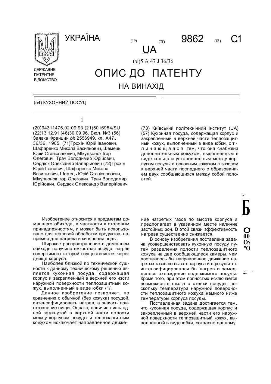
Номер патенту: 9862
Опубліковано: 30.09.1996
Автори: Шафаренко Микола Васильович, Сердюк Олександр Валерійович, Шемець Юрій Станіславович, Трохін Юрій Іванович, Трач Володимир Юрійович, Мікульонок Ігор Олегович
МПК: A47J 36/00
Формула / Реферат:
(57) Кухонная посуда, содержащая корпус и закрепленный в верхней части теплозащитный кожух, выполненный в виде юбки, отличающаяся тем, что она снабжена дополнительным кожухом, выполненным в виде кольца и установленным между корпусом посуды и основным кожухом с зазором к верхней части последнего с образованием двух сообщающихся между собой полостей.
Електричний посуд
Номер патенту: 1139
Опубліковано: 15.01.2002
Автор: Глушко Сергій Валерійович
МПК: A47J 27/08, A47J 27/21
Мітки: посуд, електричний
Формула / Реферат:
1. Електричний посуд, що містить ємність з кришкою і щонайменше однією ручкою, і електронагрівник, розташований у нижній частині ємності, з утворенням її дна, який відрізняється тим, що ємність і кришка виконані з можливістю герметичного прилягання один до одного й оснащені притискними засобами, причому кришка має один або декілька отворів для зв'язку з зовнішнім середовищем, а дно ємності виконане подвійним у вигляді порожнини, заповненої...
Попередній патент: Спосіб відновлення та плавлення металу
Випадковий патент: Спосіб виготовлення деталей типу "дифузор" методом локальної деформації